It’s been a while since my last post! Every once and a while, I get a chance to sit down and work more on my power monitoring project. Previous versions of this project have been operational and collecting data for well on three years now, but I’ve wanted to clean up the physical design a bit and make it more usable.
A quick recap of this project – my dad and I wanted something to monitor power usage in the home by each individual circuit in the house. Read about how these type of systems work at https://learn.openenergymonitor.org/.
- I selected the Teensy 3.2 as my primary microprocessor to do ADC sampling and conversions as it has 21 ADCs
- Selected the ESP8266 WiFi module to send gathered data to a database somewhere (using a local installation of EmonCMS on a Raspberry Pi)
- Selected the Texas Instruments REF2033 as a voltage bias source (it’s expensive, but very nice for this application)
- Used EAGLE to create schematics and the PCB layout
- Sent PCB design files to SeeedStudio to be manufactured
- Designed an enclosure in Fusion 360 with a snap-fit lid
- Wrote (well, writing…) the code in the Arduino IDE
A while back, North Carolina State University cut me off from using their Solidworks license – which makes sense – I graduated five years ago! In lieu of Solidworks, I picked up Fusion 360 at home (I use CATIA V5 at work).
Since I last used EAGLE, it was purchased by Autodesk and woven into their portfolio. As such, EAGLE now supports some 3D CAD integrations with Fusion 360. I’ve completed a revised version of my power monitor PCB layout – shown below in both EAGLE and Fusion 360. The combo of these two programs makes modeling PCBs and their supporting enclosure/structure very easy.
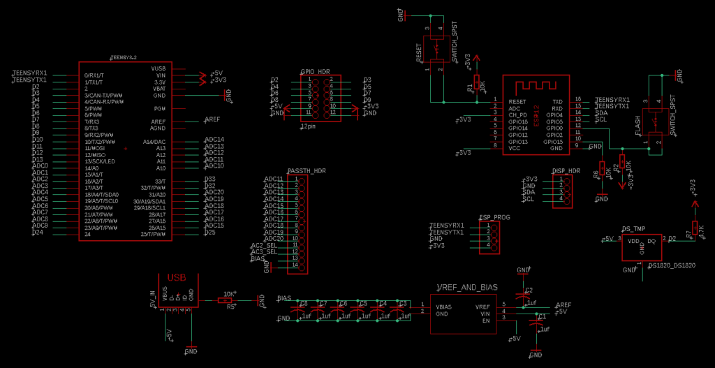
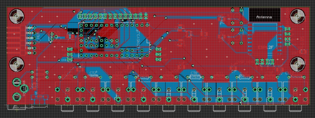
Once you have the PCB design complete, you can go in and update the 3D model of each component in EAGLE. You upload and position a custom model in the EAGLE interface. The interface to do this is a bit confusing, but I hear it will be getting better and more straightforward in the future.
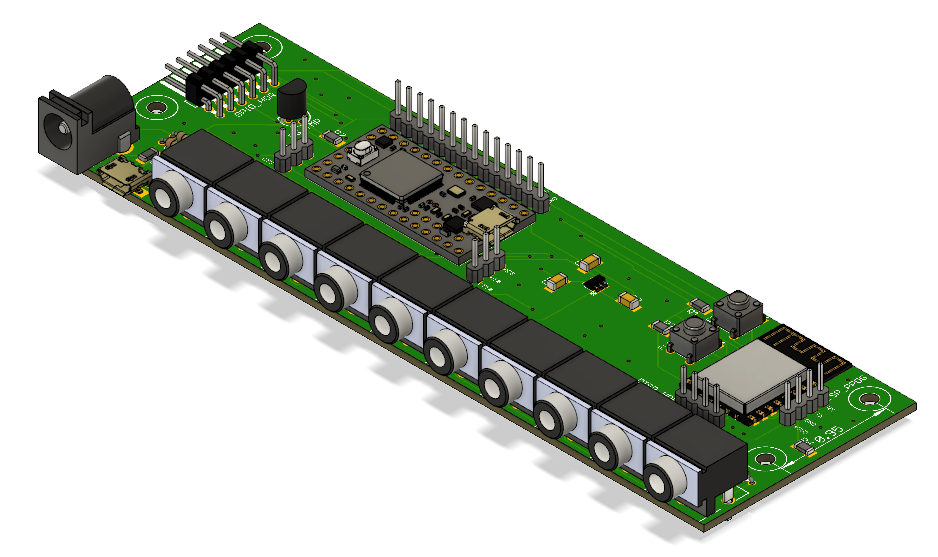
Then, you click a button in EAGLE that pushes the model to Fusion 360. As you can see below, if you’ve routed all your traces, it even shows them on the board, as well as all vias and other tiny details. It’s actually pretty sweet.
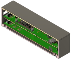
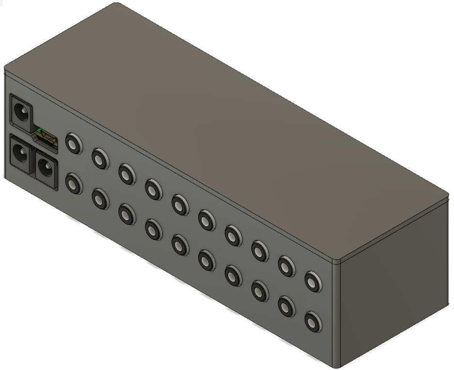
This is what makes modeling enclosures super easy. In Fusion, you can actually project the board components onto sketches to drive geometry. Here’s a simple box I was able to come up with after couple of nights tinkering around:
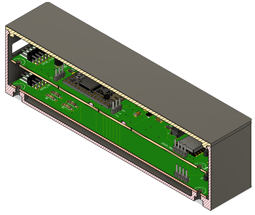
And for reference a section analysis:
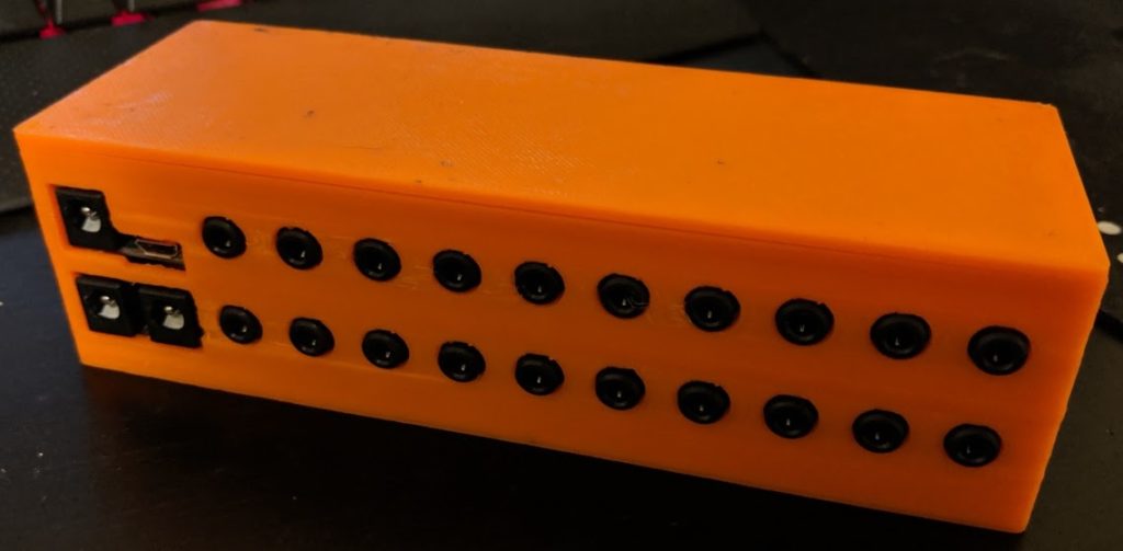
Sliced it up and printed it on my Qidi Tech I (A Flashforge/Makerbot clone):
Now to update the software that runs on this bad boy…
