This is something I have wanted to do for a long time, and now that we own a house, this was the year we made it happen. We got permission to operate from the local power company on March 27th, 2024. I probably started my plans/design and applying for permitting in mid-January of that year.
What’s all involved in doing a DIY, grid-tied rooftop solar installation?
Well, that’s what I’ll get into here – I’ve tried to document my process. Not sure who the audience here is, but figured I’d write some stuff down.
Keep in mind that the requirements vary on where you live – power companies, states, municipalities, and counties all can impose their own requirements. Thankfully, I’m in unincorporated King County in Washington, and the requirements here made things easy – at least permitting wise.
Permitting and Utility Company Permission to Operate
This part of the process is important to do in tandem with your design phase, so you can gather and apply the necessary information to your permits, utility company generation site application, and design.
Building Permit
Do the building permit research early on in your design process. Many of the parameters like roof setbacks, maximum allowable size or power, electrical requirements, etc are crucial to getting it approved.
Washington State Building Code Council publishes what codes we follow here in WA, basically amended versions of the IRC/IBC. See https://sbcc.wa.gov/state-codes-regulations-guidelines. Counties and municipalities can also amend these. I did some reading to make sure my design would meet the code, even though it turns out we don’t need a full building permit for rooftop solar here.
In my jurisdiction, rooftop solar installations are exempt from a building permit if you document meeting a few criteria and retain the completed form, in case anyone comes asking. See below.
Note things like meeting IRC sections, keeping it under 3psf additional roof load, keeping each attach point under 50lbs point load, and a few other things. We’ll talk more about this during racking design.
Gather your design loads. You’ll need this for racking design, and definitely your building permit application if your area requires that.
- Some jurisdictions will rely on something like ACSE/IRC/IBC for ground snow load/wind/seismic design category zones. Others will spell it out in their state laws/county titles/city ordinances. In my case, King County lays it out in their rules and titles:
- Snow loads in King County: https://kingcounty.gov/vi-vn/dept/local-services/buildings-property/development-planning-regulations/public-rules, see rule 16-04 ‘Structural Loading: Minimum Roof Snow Loads’. In my area, I’m at 25psf.
- Wind loads – set by King County Code Title 16.05.040. This sets the wind load to 110mph.
- Seismic Design Category – also set by King County Code Title 16.05.040. I am in D2 (the worst one).
Power Company ‘Permission to Operate’
Most power companies have a website or similar process for applying to be a solar generation site. Puget Sound Energy (PSE) the electric utility in my area, has a website where they talk about it and lay out the requirements for applying.
- Requirements include a one-line diagram, disclosing your panel and inverter models, and a few other tidbits. I’ll talk about the one-line diagram a bit later.
- The application website is here. You’ll eventually have to upload proof of your electrical permit being approved, a few signatures, and some system design specifications.
- Because you’ll need quite a bit of info for this, you can’t (or shouldn’t apply for this right away, do some system design first!).
Electrical Permit
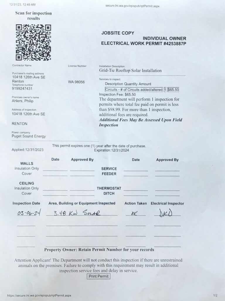
Because I found out that the utility company requires an approved electrical permit prior to granting ‘permission to operate’ (PTO), I had to do some research here on who grants electrical permits in my area. Since I’m in unincorporated King County, the Washington State Department of Labor and Industries issues these.
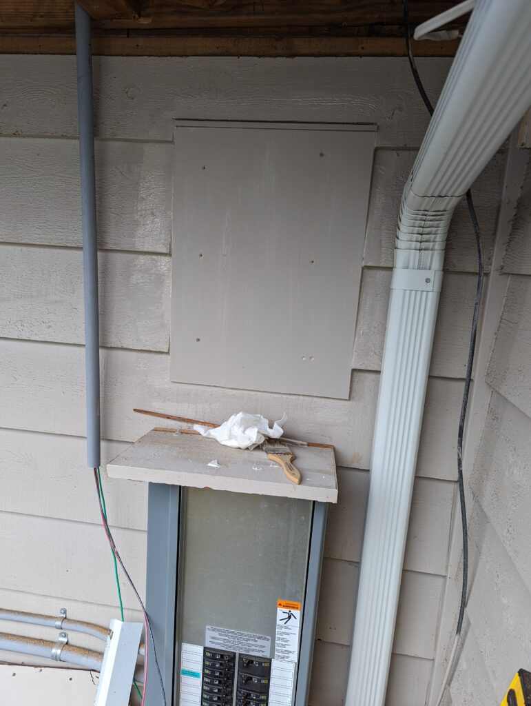
The WA Dept of L&I also publishes what version/amendments they make to the NFPA 70. See https://lni.wa.gov/licensing-permits/electrical/laws-rules-policies. We are on NFPA 2023 here, so do some reading to make sure your electrical installation will meet all those requirements so your inspection will go smoothly. Some power utilities also have requirements for disconnects and other required electrical features.
Do some research on what parts of the code you’ll have to meet – you’ll need to size breakers, wire gauges, etc to ensure you’re meeting this. You’ll also need to read to see if you need a dedicated disconnect switch outside, and a few other things. Since the permit is good for a year, I applied/purchased the permit right away, and then after it was all installed I submitted to have it inspected (which I passed first try, by the way).
My inspector also wanted a copy of my one-line diagram that I submitted to the power company. I had a paper copy available for their review.
High Level Design – Picking Panels/Inverter(s), Roof Placement, One-Line Diagram
First – have a rooftop that is conducive to solar. Some houses have wild rooflines, no good south-facing roof, etc. Here’s what my current roofline looks like:
Our roofline as of August 2022. I used our south-facing garage roof for the solar install.
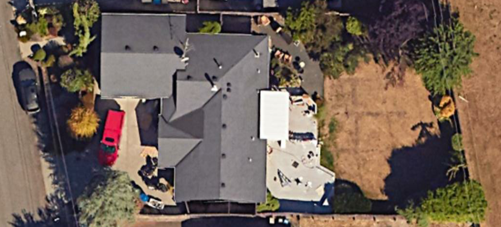
In the northern hemisphere, it’s best if solar arrays (if tilted) face south, for maximum capture of the available solar irradiance. I picked our south-facing garage roof.
Measure your roof (you can either do this in something like Google Maps/Earth, or just get up there and measure. I went up and measured to get the exact dimensions, and to measure the slope of my roof. Since I planned to place panels on the south-facing garage roof, I measured those dimensions and also the pitch. That roof is a 4:12 pitch. You’ll need this information a lot for your design, so write it down!
I used the super-nice IronRidge configurator website to lay everything out and help with research and design. Check out the below image and the full report in the racking design section of this post.
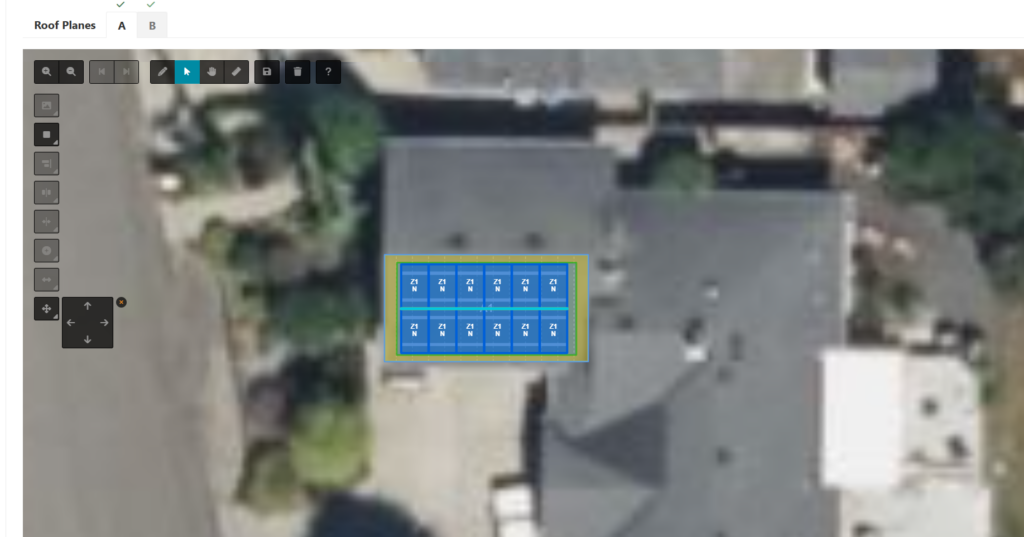
A sample of the online IronRidge configuration tool. The tool lets you pick panels, layouts, and will help you with code compliance.
Because the IronRidge configurator has a large database of solar panels and their dimensions, you can cross check to what equipment and panels are available in your area, and iterate with different panels to get the most wattage of panels on your roof. I ended up sourcing panels from an electrical supply house here in the PNW called Platt, but more on that later.
- Use panels that you can actually get. Preferably locally, to save on freight.
- Experiment with different layouts, orientations, panel sizes, panel models, etc.
- Keep in mind that the most utilization of your roof may not be the largest wattage panel – you may be able to tetris in more smaller panels better than fewer larger panels. It’s all about the best usage of the available square footage.
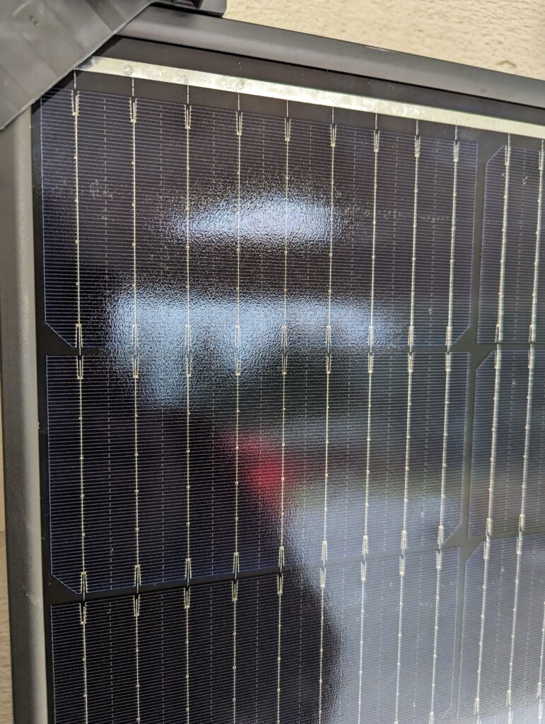
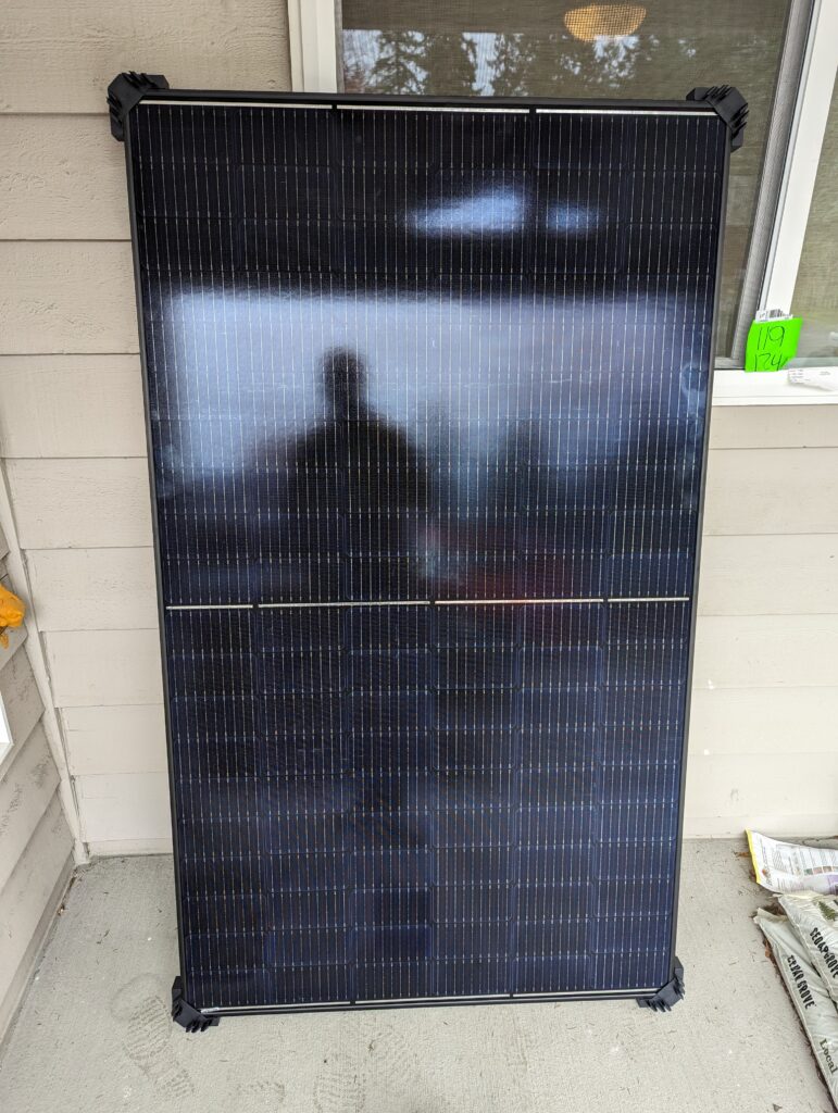
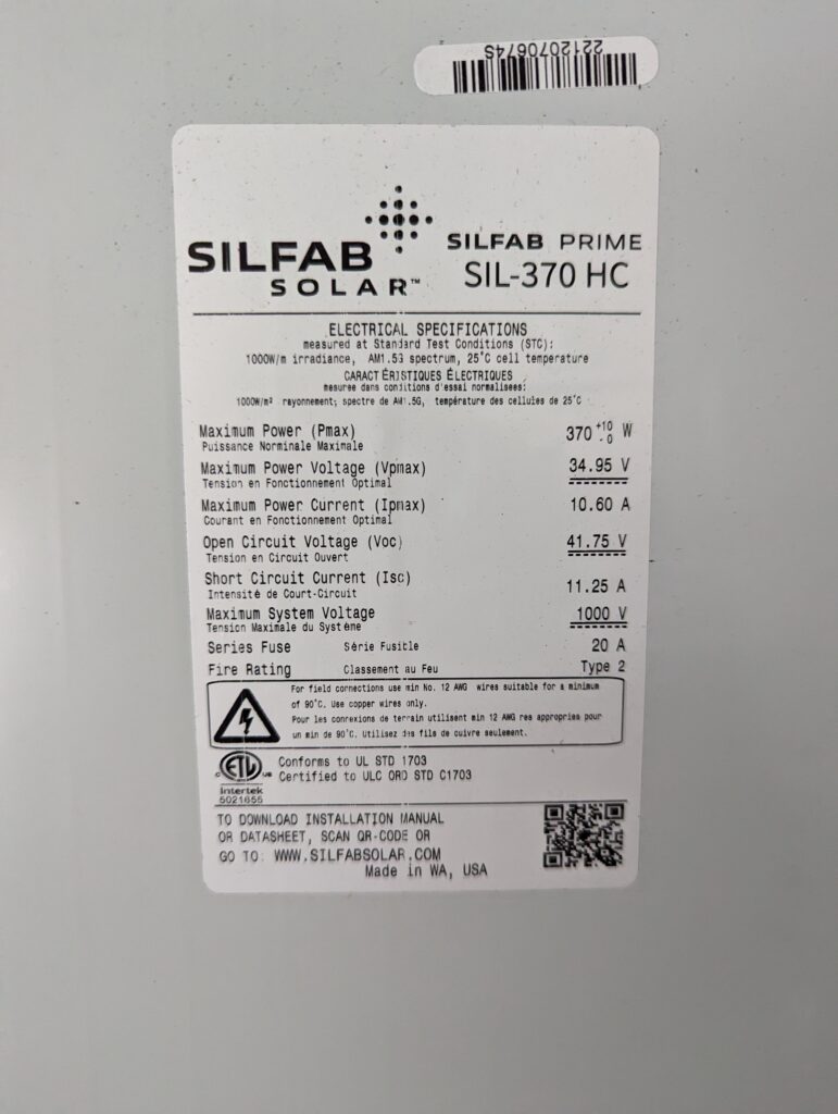
I landed on a locally available (and locally made, actually) solar panel – the Silfab SIL-370HC. Turns out those panels are made just north of where I live here in Washington. For now we’ll ignore any racking hardware – just use the configurator to play with solar panel layouts only.
Now that I knew about what my system would consist of – Twelve (12) 370 watt panels (that means 4.44kW DC capacity) – I could start to research or pick inverters, microinverters or string inverters. For this, I used both the inverter vendor websites and software available from the National Renewable Energy Laboratory (NREL).
The System Advisor Model (SAM) software available from NREL is basically the extremely detailed version of PVWatts. SAM includes databases of solar panel performance data, inverter performance data, solar irradiance data, and much more. You can input cost data, actual or simulated usage data, and the software calculates outputs including ROI or payback time scales, total output, clipping data, and much, much more.
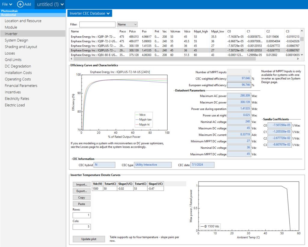
System Advisor Model (SAM) – You can see that the software comes with built-in databases of performance data of many inverters.
After doing a lot of internet research, hearing coworker experiences, and analysis in SAM, I decided to go with microinverters – or a single inverter for each panel. They are located under each panel on the roof. Based on my location, panel size, and other factors, I picked the IQ8+ Microinverter, part number IQ8PLUS-72-M-US. Why did I choose microinverters?
- Ease of installation – they attach to the racking under the solar panel (no big inverter to mount inside or on the side of the house)
- No high voltage DC (>100 VDC) wires that I can’t deenergize on my roof. It’s decently safe to set these up in full sunlight.
- Cool per-panel metrics and data
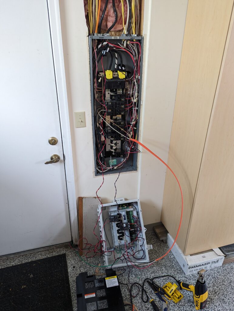
- Wiring simplification – since the microinverters output 240VAC, all you need to do is run two wires into your main electrical distribution panel from the inverters
- They are a bit more expensive per watt than a single inverter or string inverters, but I think that is outweighed by the above
You’ll notice that my panels are rated at 370 watts nominal, and the microinverters I picked are rated at 290VA continuous or 300VA peak – why?
Basically, a solar panel rarely operates at the nominal or peak output that the panels are rated for. Only during low ambient temperatures and high solar irradiance (think July sun, but 55degF outside) are panels operating at their maximum rated power. Normally in July with the most solar energy hitting the earth, ambient temperatures are also high. As temperatures rise, solar panels decrease in efficiency – so now a 370 watt panel is only going to output 330 watts, for example. You can see those curves in the data available from the solar panel manufacturer, and SAM uses that data to calculate what is known as ‘clipping’, or when your microinverter will saturate, leaving a bit of that solar panel capacity on the table. You can do more reading on solar panel ‘clipping’ from various places, I know NREL has produced some papers on it.
Essentially, that tiny bit of energy you lose by sizing smaller microinverters is more than offset by the reduction in cost of the smaller capacity inverters. SAM showed clipping losses for me was <1% with this configuration.
So Twelve (12) 290VA microinverters means 3.48kW of AC capacity.
We have spec’d out our panels and our microinverters – the two main components of a rooftop solar array. Keep in mind that this data will be required for the electric utility PTO application.
So now that we know our components, it’s time to put together a ‘one-line’ diagram. Not only does the utility company require this as part of the application, my electrical inspector asked for a copy when they arrived onsite, and it generally just helps you understand what’s going on. The below is an example (not exactly what I submitted, but very close). Keep in mind it’s just a ‘one-line’, we are not showing each individual electrical conductor here.
I’d go ahead and apply for the utility company permission now, as we have initial sizing and component selection done, and have our one-line complete.
Racking Design and Bill of Materials
For the racking design, I went with IronRidge, partly because of their awesome website, and partly because a coworker had recently used them and had a good experience. Overall, I was super impressed with the IronRidge setup – it truly did make everything very easy, the components were very high quality, and I felt really good about the install itself.
Since we’ve got all the research done on the building code requirements, and know our design loads from research earlier, we can input all that data into the IronRidge tool.
You’ll need to verify a few things during your planning in the tool. First, meet any applicable building codes – for my area, I had to ensure the total distributed load was less than 3psf, and any individual point load was <50lb. My installation ended up being around 2.5psf, and a maximum of 37.1lb point load.
If you look a the last page 8 of the above report, you can see the tool even gives you a bill of materials for your racking! I used this and purchased all the components at a local electrical supply house, except for the wire clips, which I found online.
Inverter Related Bill of Materials
The Enphase System Builder website helped with knowing about those extra components required, as well as a bunch of research there.
I went ahead and put together my Enphase-related bill of materials, since I was going to order most of that stuff online. The below is an output from the Enphase System Builder, linked above.
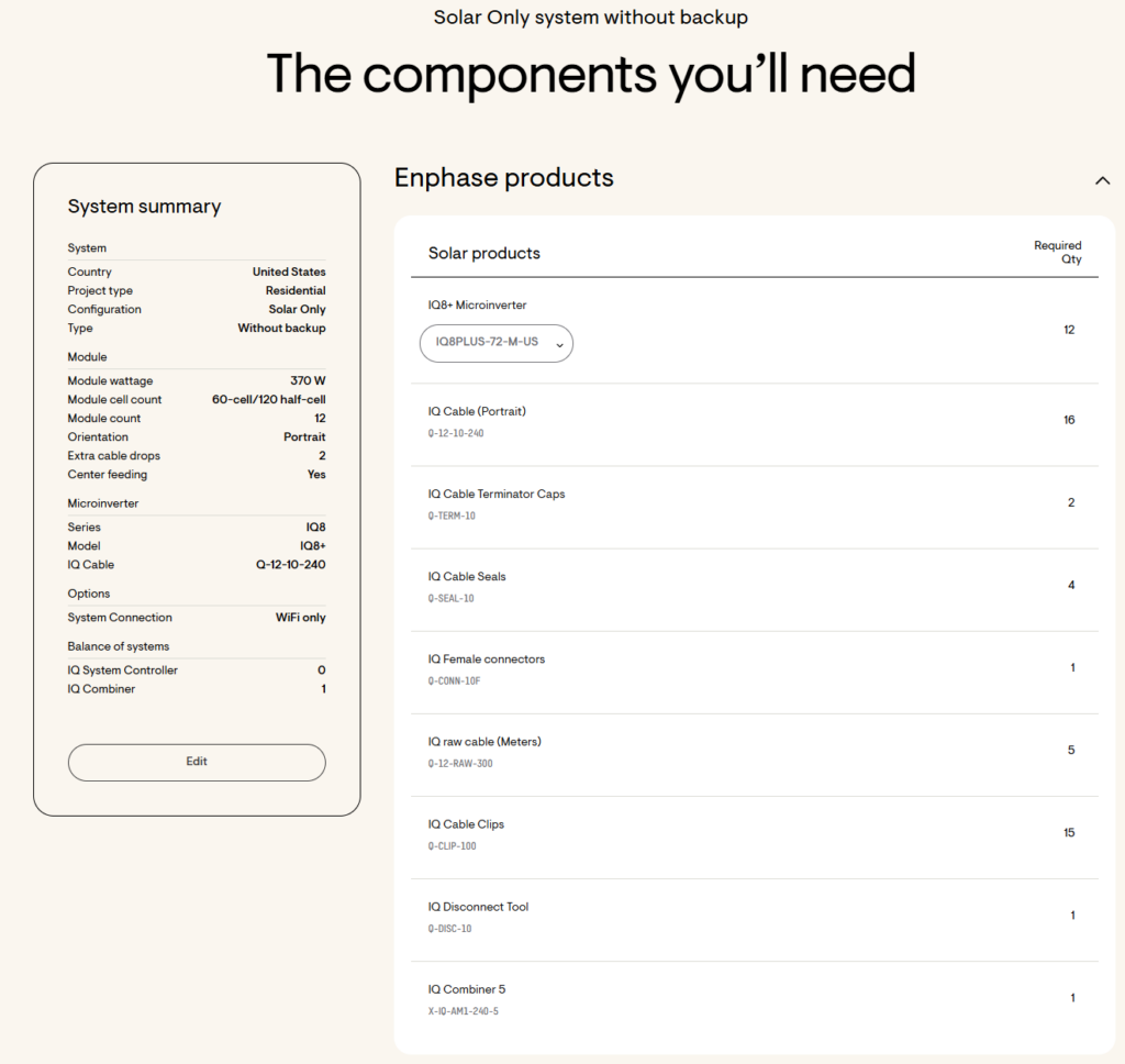
I ordered the microinverters, the IQ cable (the cable that connects the AC output sides of all the inverters), and the associated IQ cable caps and seals all directly from Enphase. I found they had the best or most competitive pricing for that stuff. I did not order any IQ cable clips from them, nor the disconnect tool. For the clips (these are used to attach cables to the racking) I found some stainless trailer wire clips on Amazon, and for the IQ disconnect tool, I found one on Ebay.
- Keep in mind that there are different type of the Enphase IQ Cable depending on your panel layout and orientation. I went with portrait cable.
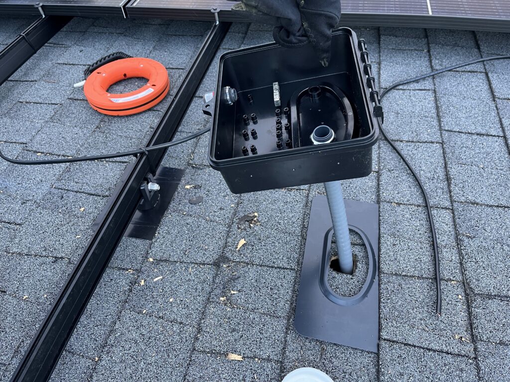
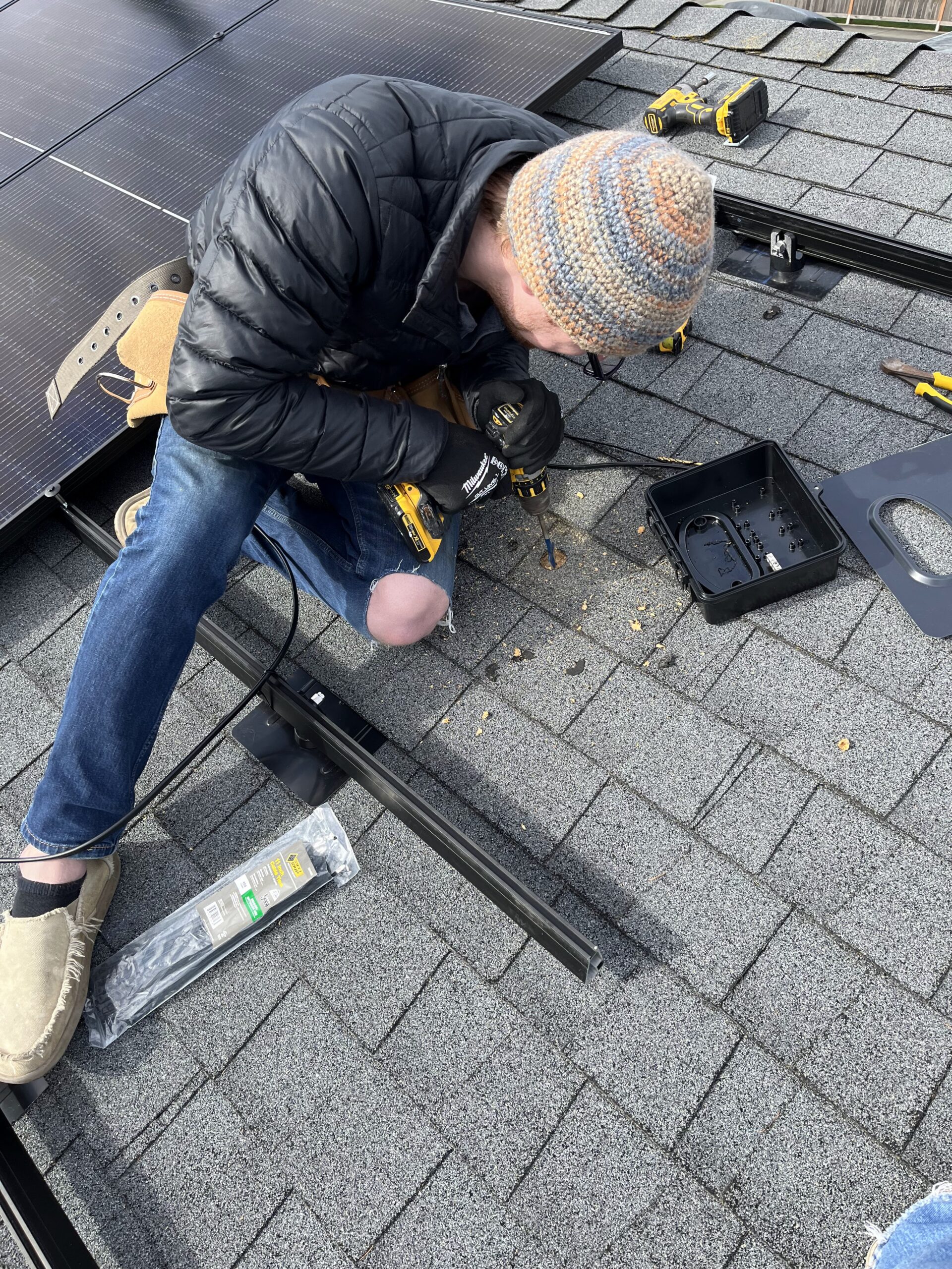
- Have a rough idea of where you’ll be placing the junction box on the roof. I ordered a couple extra connector lengths of the IQ cable to plan for that. There will be photos of the installation later.
- I didn’t end up getting any ‘IQ raw cable’ or IQ female connectors. My IQ Cable was long enough to reach my rooftop combiner box.
Procurement and Sales Tax Exemption
I now had an electrical permit from WA L&I, and approval to construct from PSE in hand, so it was time to get to work.
My box from Enphase was packaged well, and had all my inverters and cabling.
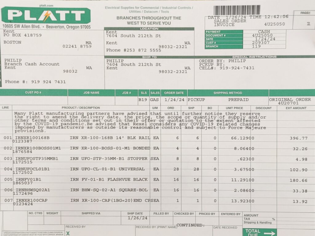
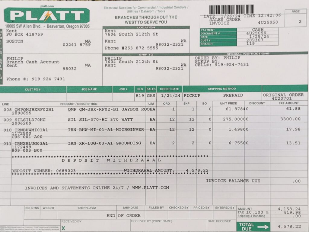
I drove over to Platt, a local electrical supply house, and ordered everything I needed in person. Ordering through their website doesn’t allow you to pick up orders, only ship them (for extra cost). Everything was available to pick up the next business day. No solar panels were broken or cracked, and they even forklifted them into the back of my F-150. l ended up keeping them back there until the weather was nice enough to start the installation. A photo of my sales receipt from Platt is in the photos portion of this post.
Ah yes – in the state of Washington, residential rooftop solar installations are exempt from sales tax. You can either show the retailer/wholesaler you form, or go back and apply for a refund from the state after the fact. See https://dor.wa.gov/taxes-rates/tax-incentives/tax-incentive-programs#Solarenergysystemsalestaxexemption
Installation
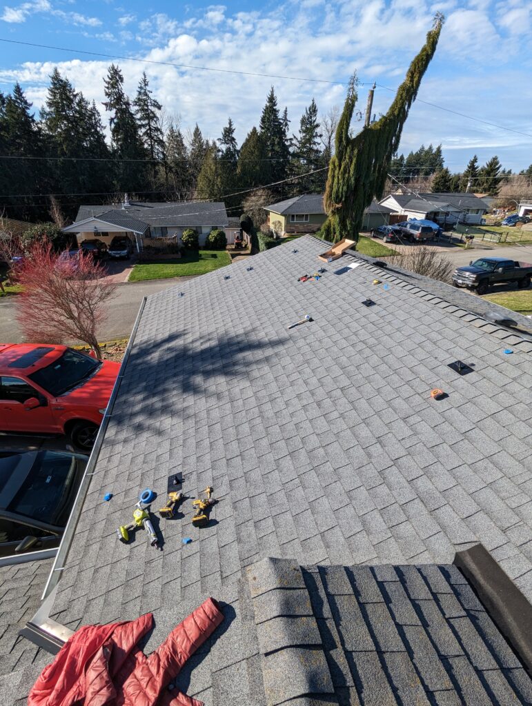
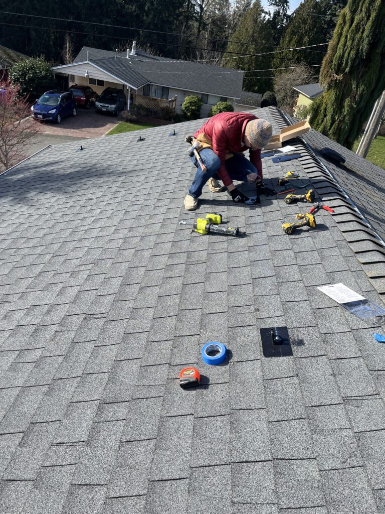
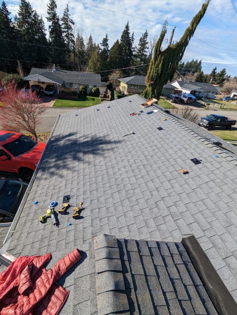
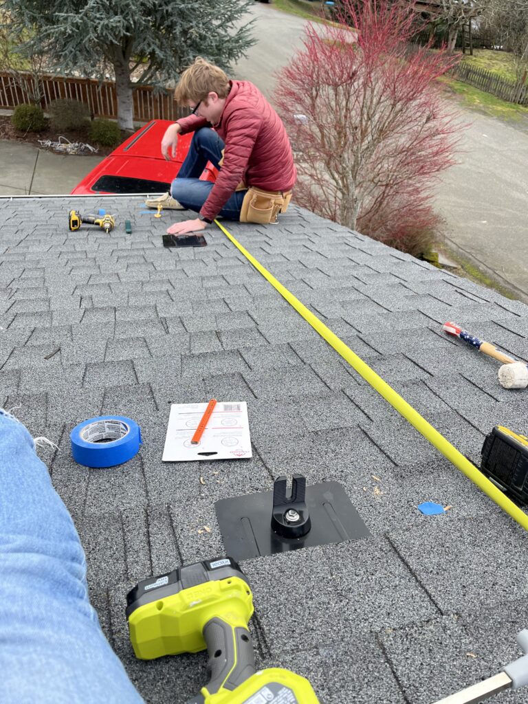
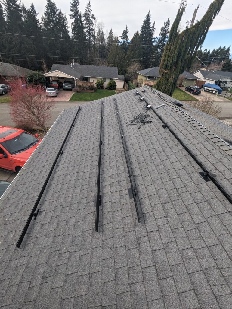
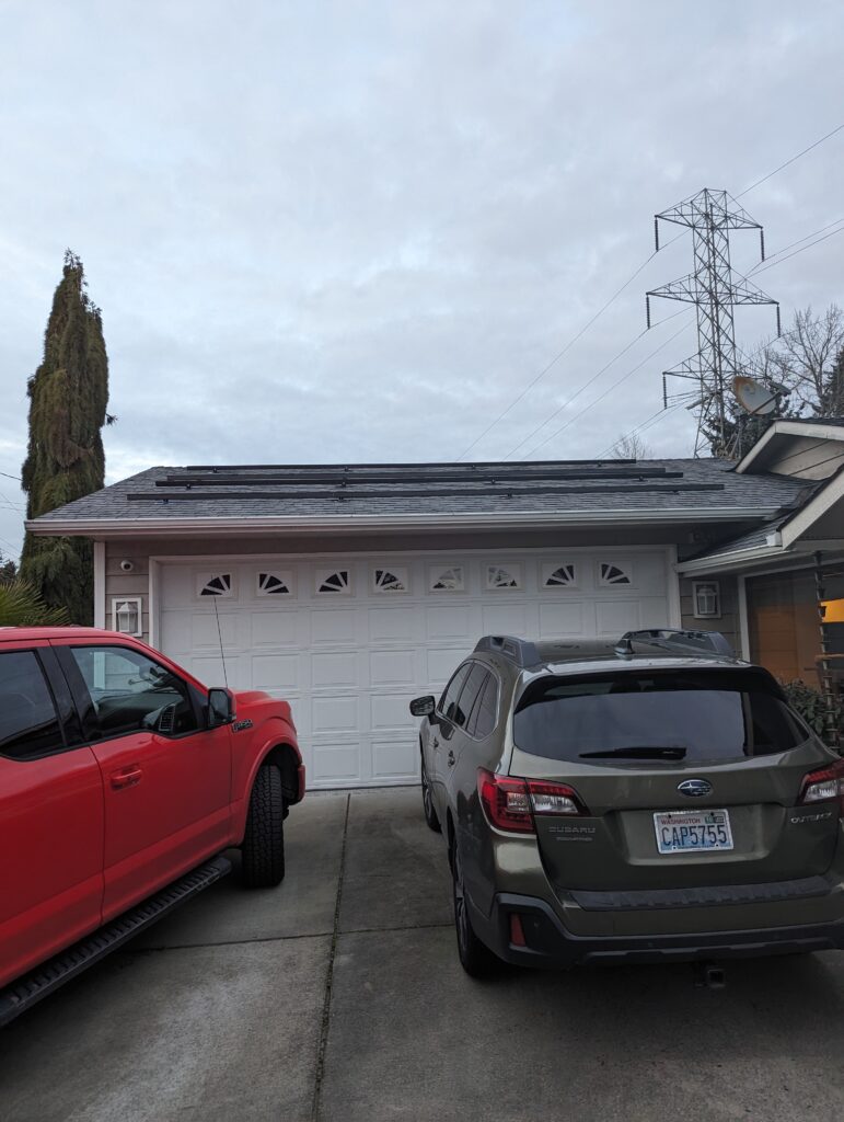
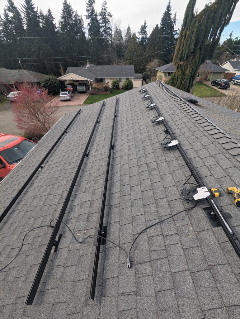
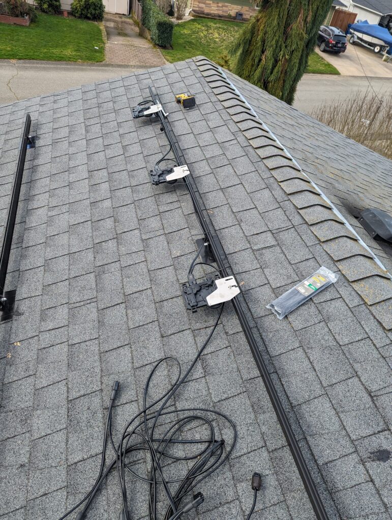
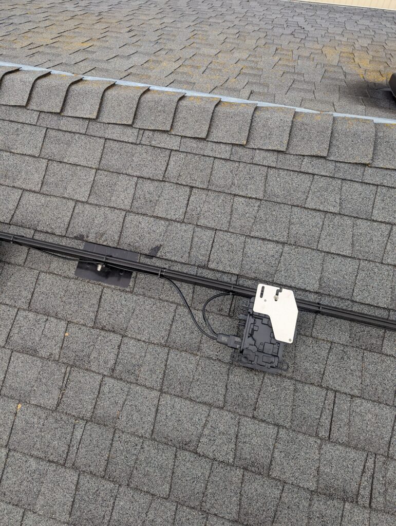
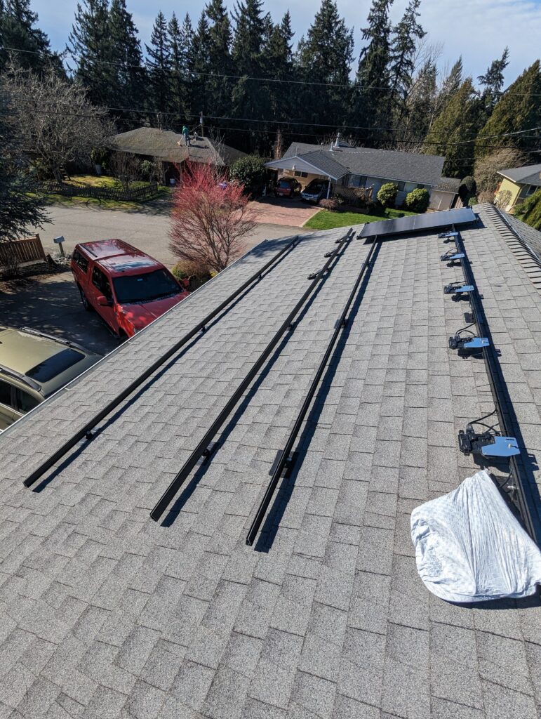
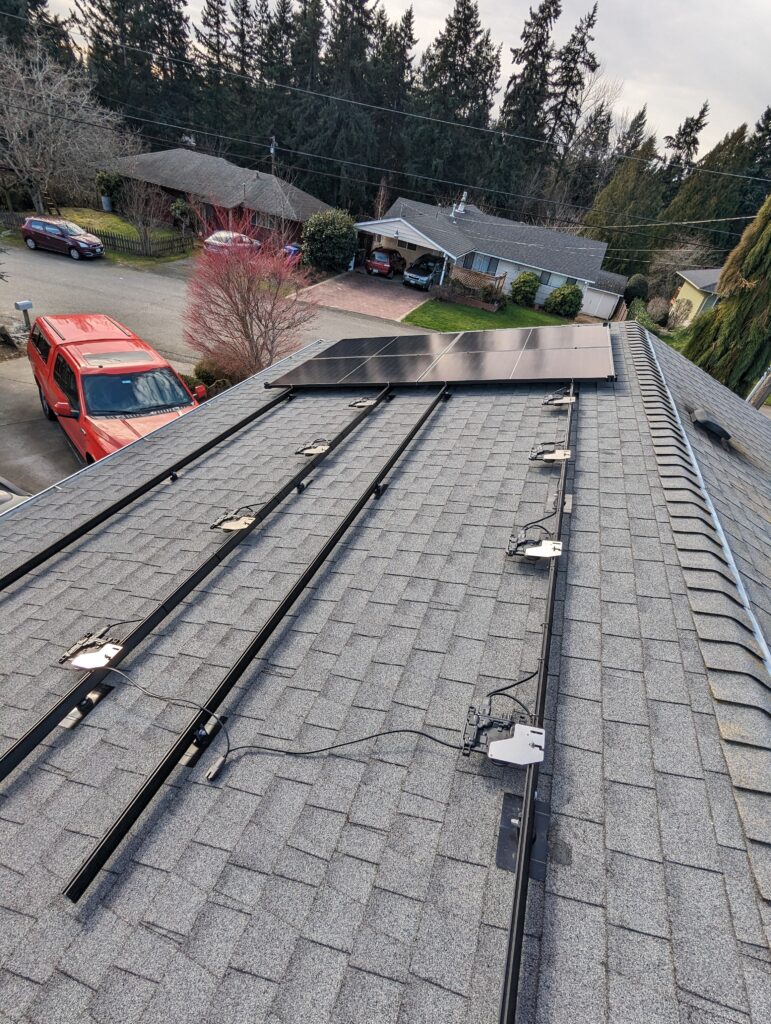
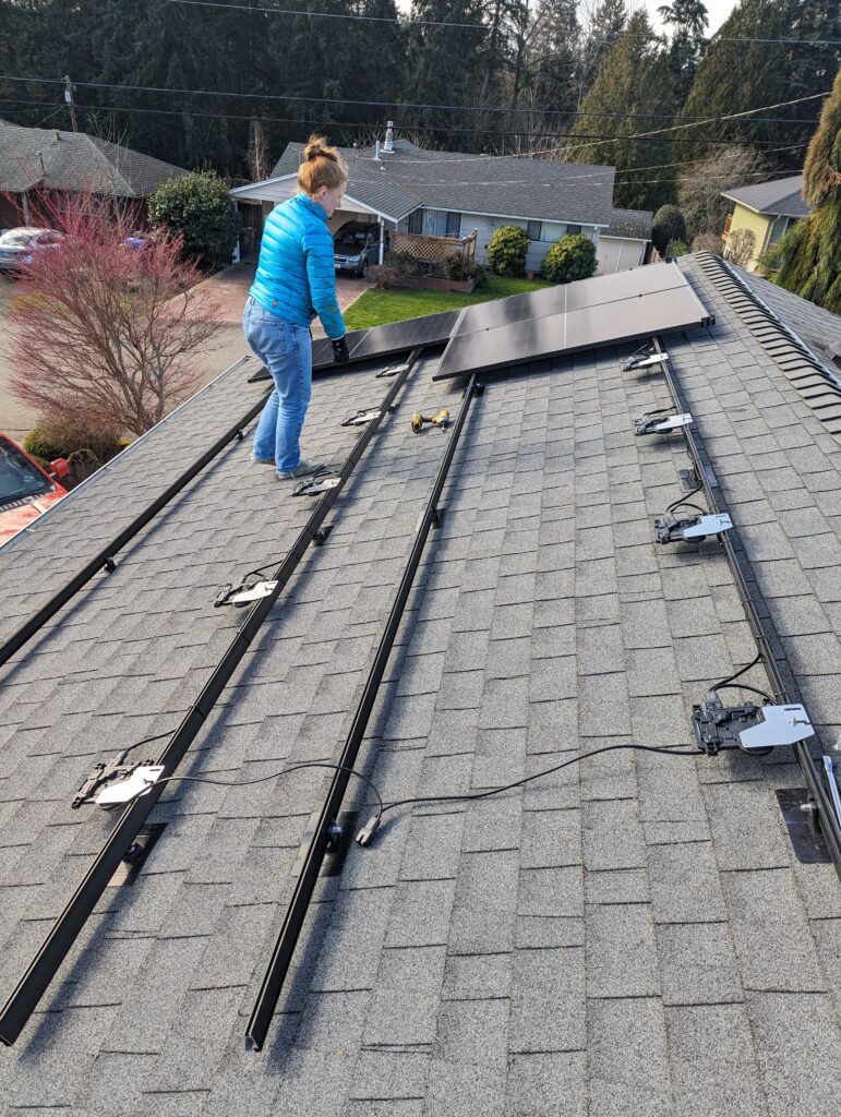
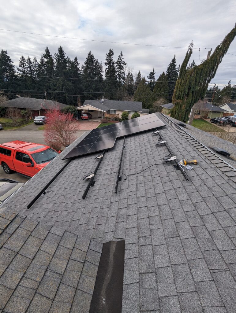
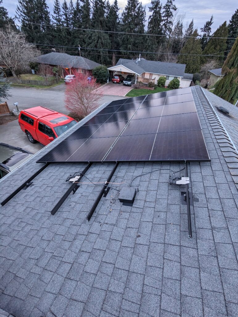
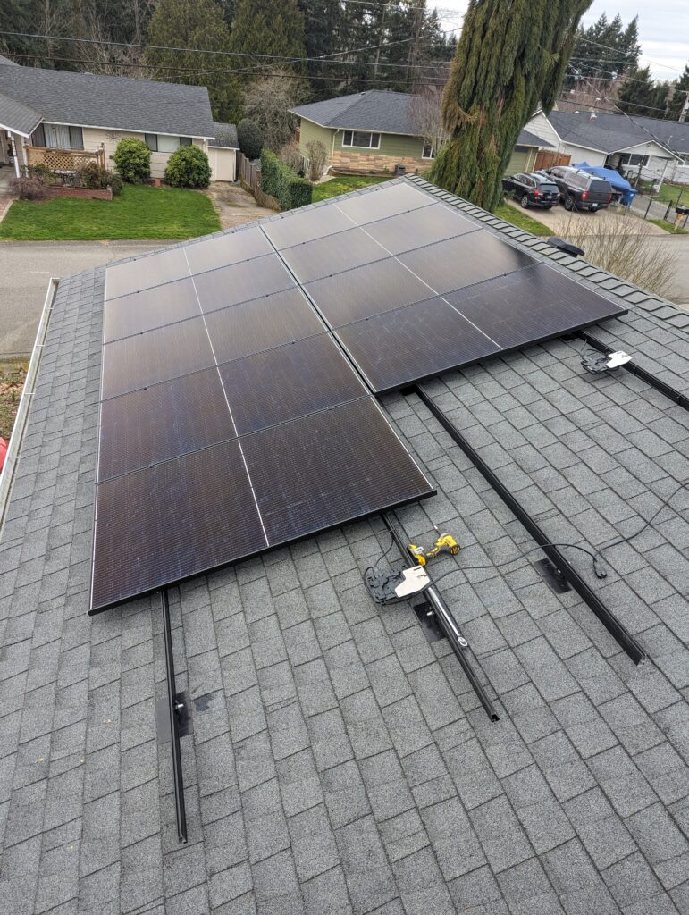
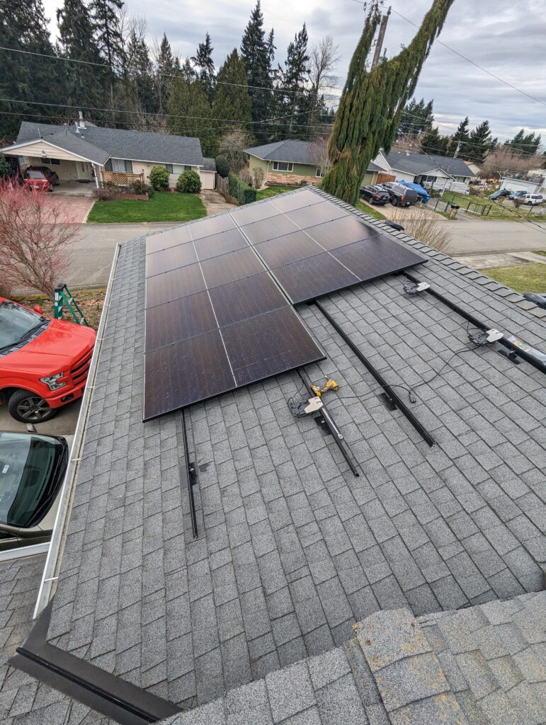
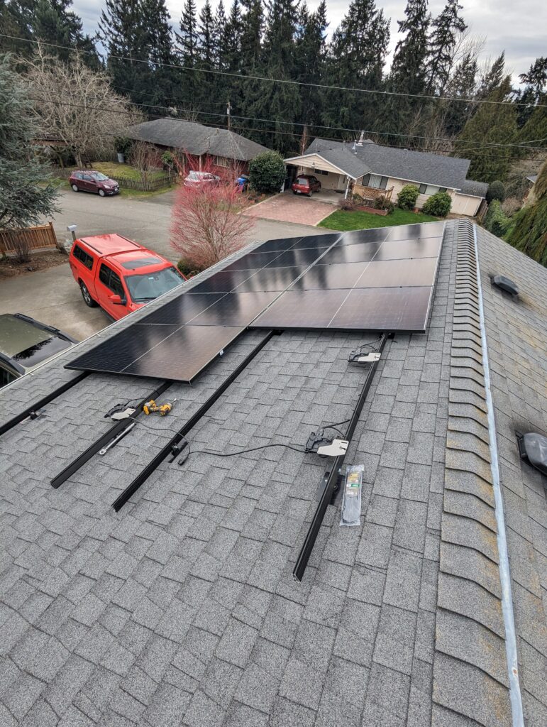
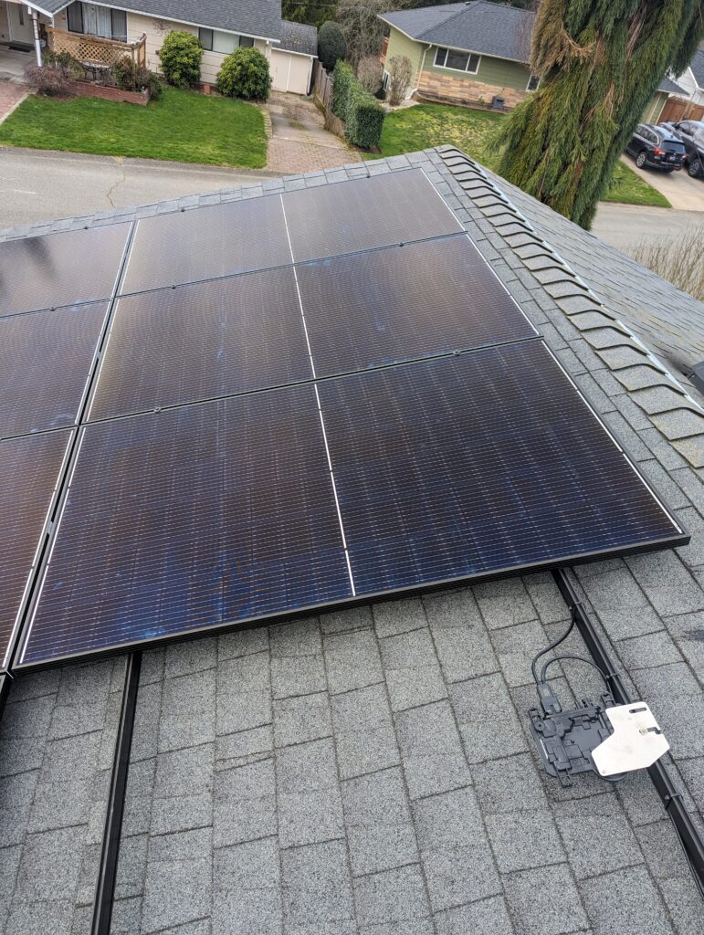
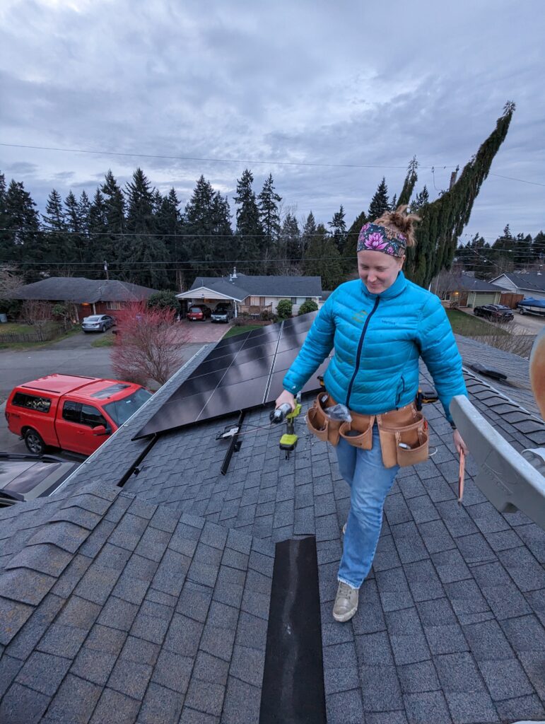
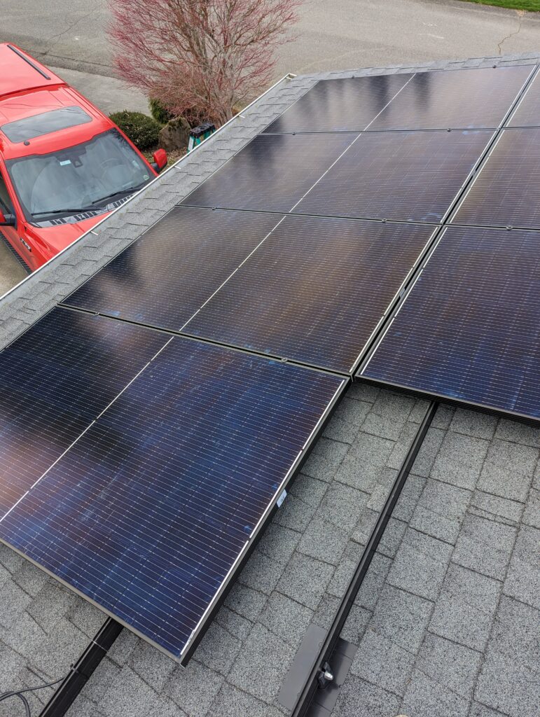
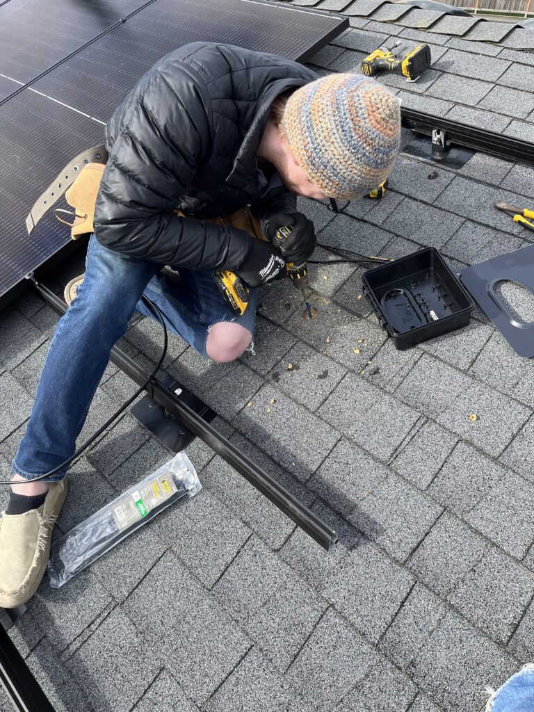
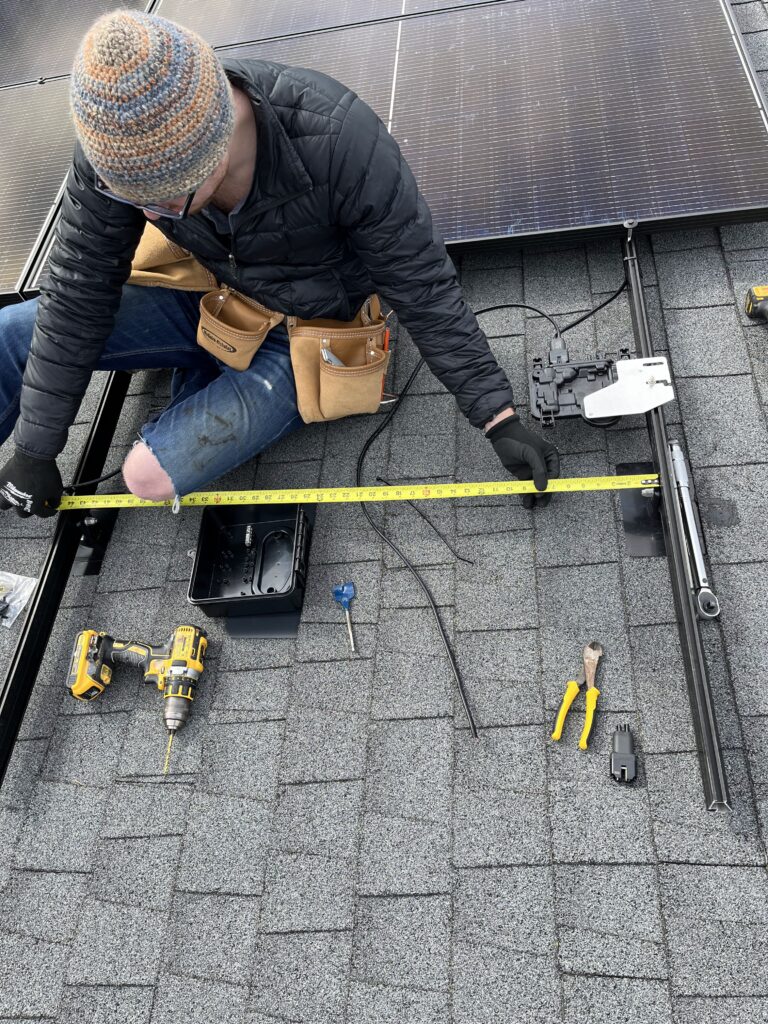
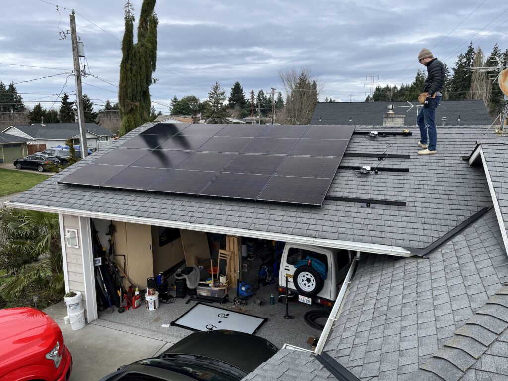
Laying out everything on the roof took the most time. Planning my mounting points with shingle locations and ensuring they aligned with what I had planned for rail spans, etc. Once that was done, the rails mounted quickly, the inverters mounted even quicker, and the panels went on fast. One thing to watch is ensuring that the first panel you mount to the rails is mounted nice and square, as it sets the rest of your panels.
The inverter cabling was super easy – the click type Enphase connectors worked well. The MC4 module to inverter also worked well. Had to tidy up some of the cabling to ensure it didn’t rest on the abrasive shingles.
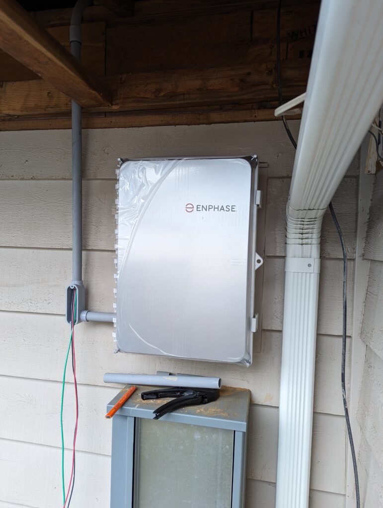
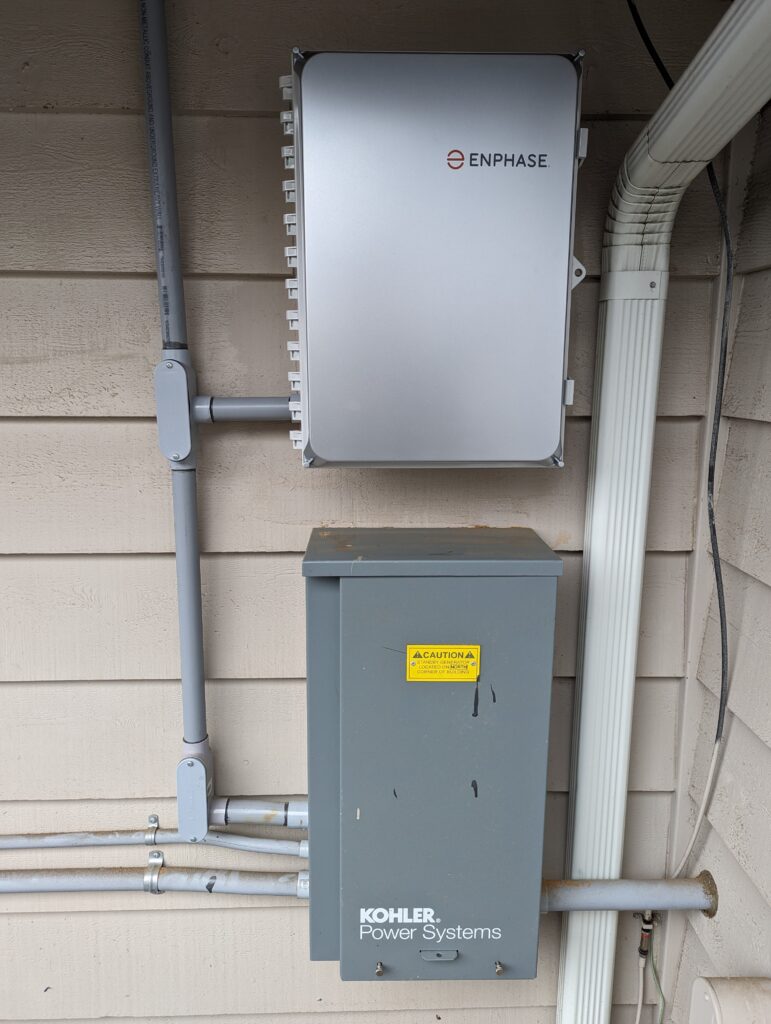
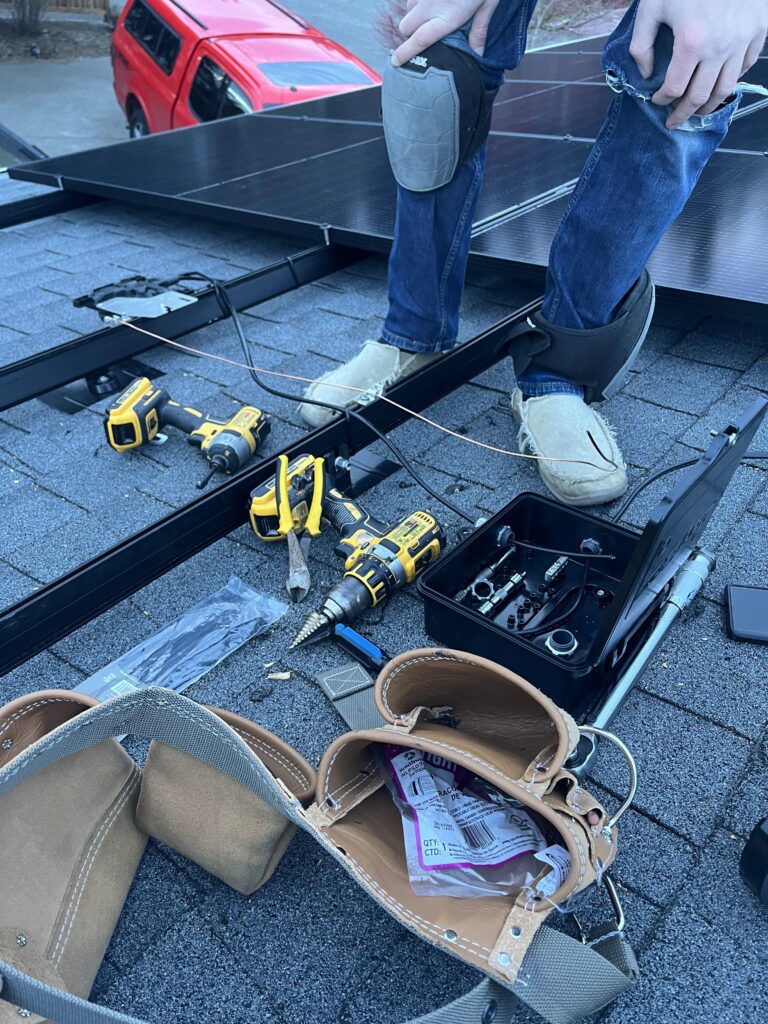
See the photos and their captions for more on the installation process.
Once I had it all installed and was testing it, I got on the WA L&I website and asked for an electrical inspection for my permit. I believe I was scheduled in the next week.
Then I sent my approved electrical permit and inspection results to the PSE to get their ‘Approval to Operate’. That took nearly a month – they do make a site visit, but I wasn’t home when they did it – no idea what they really checked. The next day I got an email saying I was good to operate.
Total Material Cost and ROI
For those curious, here’s the total cost and material breakdown:
Note that this doesn’t include the electrical permit fee, which was less than $100 dollars.
*Talk about SAM and calculating ROI here*
Photos
