Category: Arduino

  • Motorcycle Computer, Try Number 1

    Motorcycle Computer, Try Number 1

    If you check out the post Heated Jacked PWM Controller, you’ll notice that while I’ve figured out the electronics behind this, I’d yet to figure out the logistics behind a computerized controller.

    The original plan used a Raspberry Pi A+, and also used a Adafruit LCD I2C Backpack. This actually made it to a few test rides on the bike.  It worked! Well, sometimes…

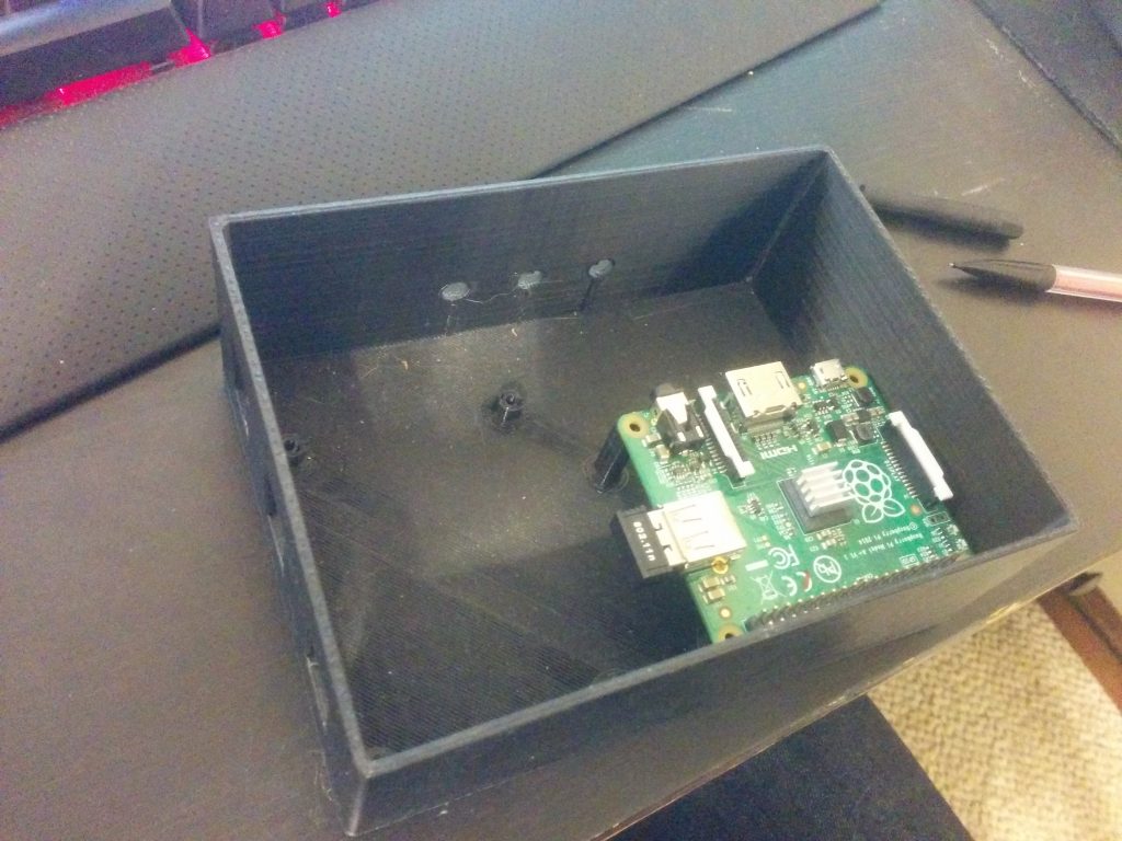
    Short story – This box sat under my seat and housed the Raspberry Pi, MOSFETs, and power supply. This is after I disassembled the first failed attempt.
    This unit mounts to my handlebars (and this pic actually has some testing going on).
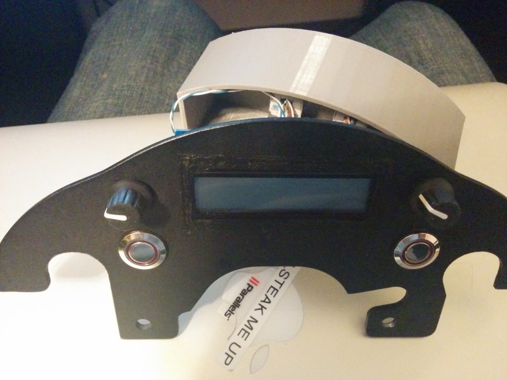
    Originally, I wanted to control the box using as few wires as possible – the screen takes six (not counting the backlight colors), and each encoder needs two, each button needs one, and buttons need ground. The I2C backpack made controlling the screen possible with only two wires, so I was able to get it down to <16 conductors, or two Cat5e cables.

    BUT – read anything about I2C (which I failed to do) – and you’ll realize a shortcoming.  It’s extremely susceptible to any magnetic or electrical interference. It’s really designed for chips residing on the same PCB.

    So the end result of the Raspberry Pi based system: it worked only when the bike was off. No kidding – without the bike on, there was no interference on the I2C lines, and the screen worked perfectly. I even had a little screen configured to graphically represent the setting of the jacket. The MOSFET worked great, and so did the rotary encoders. For a peek at that old code, see my github repository.

    If the I2C line started seeing errors and missing commands, the screen would display gibberish. Unfortunately, that was really anytime the bike was running. Turns out, metal spinning, fuel pumps pumping, and high-voltage spark plugs firing doesn’t make it a good environment for sensitive protocols like I2C (that’s why things like CAN bus exist). These I2C errors would then make my program hang.  I could have coded some I2C refreshes in, but it doesn’t solve the root cause.

    Back to the drawing board – for a hardware update.
  • Heated Jacket PWM Controller

    Along with owning a fuel-injected motorcycle comes rapid cold-weather starts, as the bike’s fuel mapping takes into account ambient temperature and other environmental factors.  Carbureted engines have lacked this auto-adjusting ability, even with the advent of electric chokes.  And with these nice, smooth cold weather starts – I don’t ever want to stop riding my motorcycle!

    So I recently purchased Gerbing heated jacket liner.  You can buy a controller from Gerbing for ~100 bucks.  But I wanted to do something a little more DIY.  If you did this right, you could build your own heattroller (as they’re called) for around ~15 bucks (555 timer, MOSFET, resistors/capacitors, wiring, but more on my build).

    Essentially, we need a way to switch the jacket on and off in varying degrees, depending on how hot we want the jacket. Why not use a variable resistor, you say? Stay tuned for a lesson on resistance and power. Switching something on and off is much more efficient.

    Enter PWM, or Pulse Width Modulation.  Some may have heard of this technology to dim LEDs, vary the speed of electric motors, or control servos in RC applications.  Essentially, a square wave is generated.  If you don’t know what a square wave looks like, see the Wiki page.  This square wave can be generated at any frequency.  Now, if the square wave spends half it’s time at max amplitude and the other half at zero potential, the duty cycle is 50%.  The longer the square wave is at max amplitude, the higher the duty cycle.  So that’s how we’ll control the on-off action of the jacket current – by increasing or decreasing the duty cycle.

    Choosing a frequency, however is interesting.  For a heated jacket, which has a lot of ‘thermal inertia’ or what I like to call it–in that it doesn’t heat up or cool down super quickly (Gerbing says it takes 4 seconds to reach max temperature) our frequency for the PWM can be fairly low.  I’m using 1 Hz.  Other devices, like LEDs, need to be driven at a much higher frequency because they don’t have any ‘inertia’ (not super sure what word to use here).  Why make it low?  Our later discussion of MOSFETs – switching losses.  Read about it here.

    But we have another problem – what can I generate the PWM signal with?  A 555-timer can be used as an astable oscillator that generates a PWM signal, with the same amplitude of what the 555 timer is powered with.  But a 555 timer can only sink about 200ma of current.  The Gerbing heated jacket liner is rated at 12v and 6.9A.  So we need a sort of relay, or switch to do the actual on-off, and a PWM signal source.

    For my motorcycle, I’m attempting to build a trip computer / recorder out of a Raspberry Pi.  The Raspberry Pi has GPIO pins which can be used to generate a PWM signal at any frequency or duty cycle.  I won’t have to fabricate a 555 circuit!  But we still will need a high-current switch.  A transistor, MOSFET, or even a relay could work at these slow PWM frequencies.  I wanted a solid state option, so I looked around for a MOSFET.

    Laying around in my electronics bin, I had a few of these:  BUZ91A.  Protip:  don’t ever buy these.  I tried to use one, and it promptly got so hot it nearly destroyed itself.  Why?  Take a look at the datasheet – the Rds(on) is .9 ohms!  That’s a lot.  And we know that

    P = V * I and V = I * R

    Thus,

    P = I * R * I

    P = I2 * R

    What does this mean?  Our jacket drawing 6.9 Amps would mean the MOSFET would have to dissipate nearly 43 Watts.  Not what you would call efficient or safe.  That would take a fairly large heatsink.  So after some looking around, I decided to purchase a few of these.  The Rds(on) is only .028 ohms.  Now, the MOSFET only should need to dissipate less than 1.4 Watts.  That’s a bit of an improvement, I’d say.  It probably won’t even need a heatsink with that load on it – especially since heated jackets are only used when the ambient temperature is <50degF.

    For more info, you can read the Wiki page on PWM.

    Or read up on some Ohms law (this site was awesome in college)!