A while ago, I stumbled upon this great organization: OpenEnergyMonitor. They’re doing a lot of things right!
Anyway, they prompted me to attempt to create a derivative of their EmonShield TX. I loved the idea, but I wasn’t sold on the RF nature that needed a base station. Since it’s easy to provide WiFi connectivity to an Arduino with the venerable ESP8266, why not make it so? Also the number of circuits (four) wasn’t exactly calling my name. I wanted the ability to do more.
So.
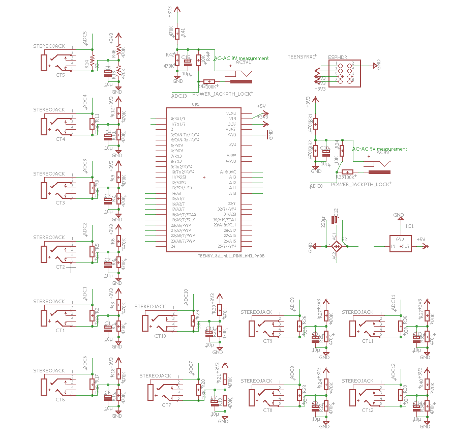
For non-intrusive current monitoring, current clamps are great. They’re simple current transformers – they themselves are coils of wire, and the conductor around which the clamp is placed forms the other coil. Thus two things are achieved – isolation and voltage step-down. However, without a burden load, transformers can be dangerous – they build up potential until they reach their insulation’s break-down voltage and fail (sometimes dangerously). So to use these, you MUST have in place a burden resistor, before clamping around a current carrying wire. OpenEnergyMonitor provides a great circuit diagram describing how to both limit the peak voltage, and bias it to remove negative potential (for measurement reasons). The burden resistor must also be matched so the peak voltage produced by the CT doesn’t saturate or exceed the limits of the device used to measure it.
Once the CT output is biased and limited to the correct voltage by the burden resistor, it’s ready for measurement by an Analog-to-digital converter.
To measure voltage, you can simply use a 9VAC transformer to provide a voltage signal (you can also use it to power the contraption). It just takes a bit of biasing and dividing, similar to the CT sensors. Again, OpenEnergyMonitor has diagrams here. If you wanted to measure both phases of common residential service, you’d need two, and thus two ADC inputs on the measurement device.
In the US, to measure a 120v device, you need 1 CT sensor and 1 ADC input. However, to measure a 240v device, you must measure both phases and add them together. So each 240v device requires two ADC inputs.
Now that we have low voltage analog signals, how to we read them? Arduino time! or… not.
An Arduino Uno has 6 ADC inputs. Not enough for me.
An Arduino Mega has 16 ADC inputs, but is rather large, and there are many reports of being unable to power the hungry ESP8266. Again, out.
The Teensy 3.2 board has many more features and ADC inputs in a much smaller package. I use the same board in my revamped Motorcycle Computer project. Its 3.3v regulator can also support the ESP8266’s power requirements. Bingo.
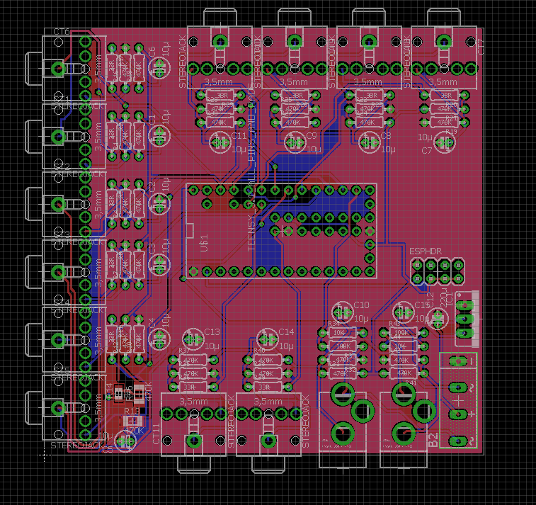
Now, for the board. I’ve been using EAGLE 7.5 to learn and play around with circuit design. Since this circuit doesn’t have any high speed signals (only 60hz AC), I don’t need to worry much path impedance or other factors in design. Here’s what I was able to come up with:

The board layout. I experimented with some surface mount components in the bottom left, but the rest of the components are all through hole.

And now that I’ve got it designed, I sent it away for manufacturing. I used SeeedStudio for my first ever self-designed PCB creation. The next update will likely be when I get these in the mail. I’ll make sure to note the turnaround time as well.

Comments
One response to “Circuit Design / Personal Energy Monitoring”
[…] last post describes a bit about the design […]