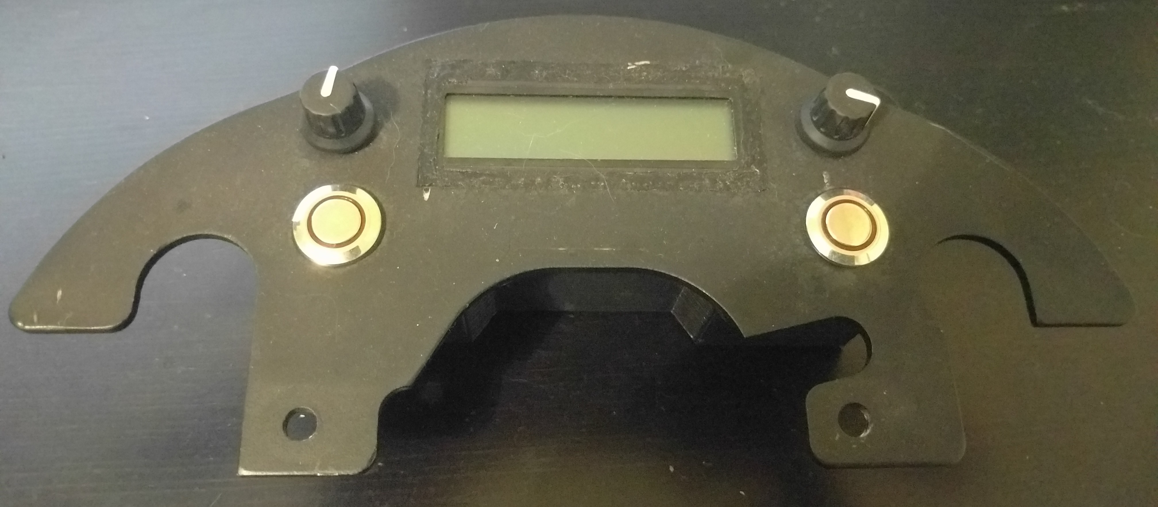
About a year ago, I made this motorcycle computer that mounts to the dash of my 2012 V-Strom 650. It controlled my heated jacket and my heated grips.
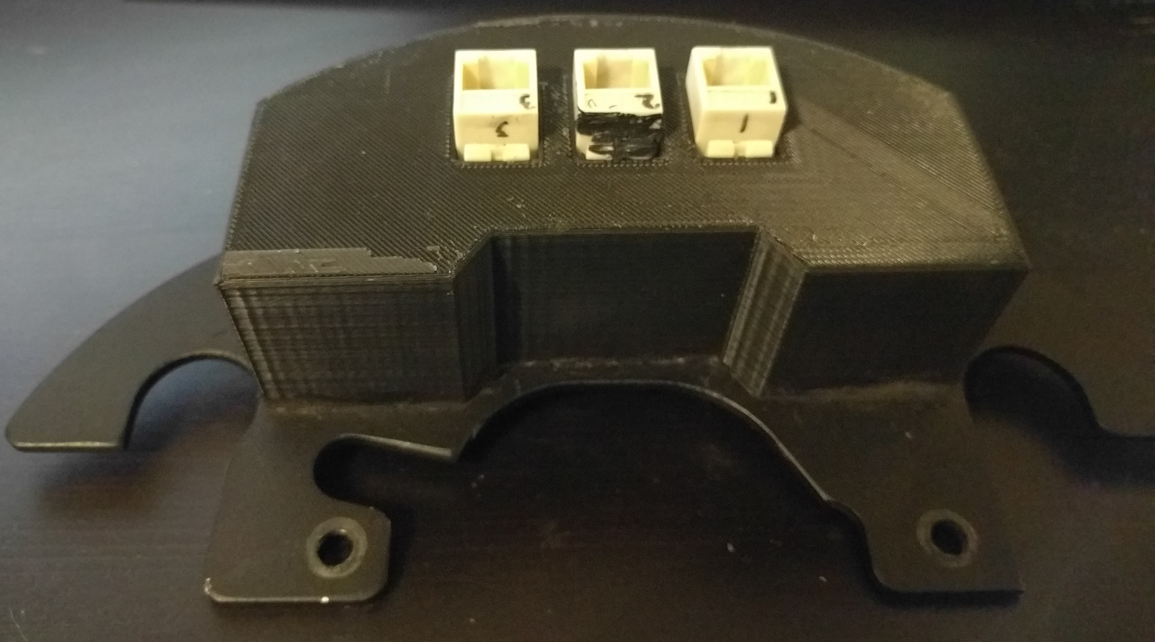
I have access to a 3D printer at work, so I modeled some housings in Solidworks and printed them out. It’s awesome – 3D printers make prototyping and hobby projects really easy! The housing is held in place to the anodized aluminum plate with standard automotive RTV.
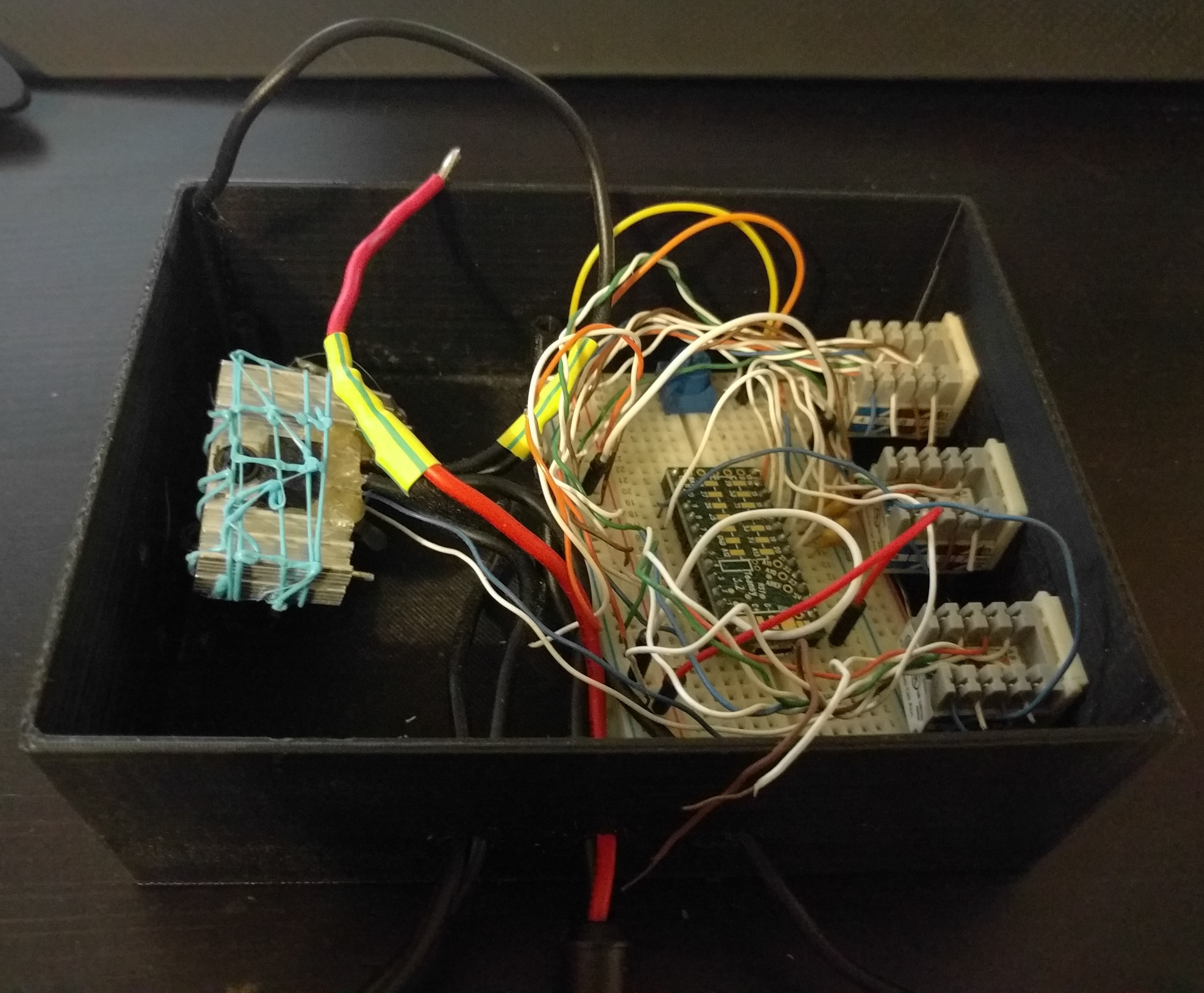
The below box housed the ‘brains’ and resided under the seat. This left the signal lines to the screen and rotary encoders exposed to a LOT of interference. My new plan is to move the Teensy 3.2 into the same housing as the screen, and make a much smaller box to house only the MOSFETs, 12v-5v DC-DC converter, and a logic-level converter to ensure the MOSFETs see a signal that is above their minimum spec to ensure the gate is pulled high.
This setup has been on the motorcycle for about a year – and no real ill effects were noticed. I never once had to fix anything. The code could use a bit of work to make the interface a more intuitive, but that’s also part of this revisit.
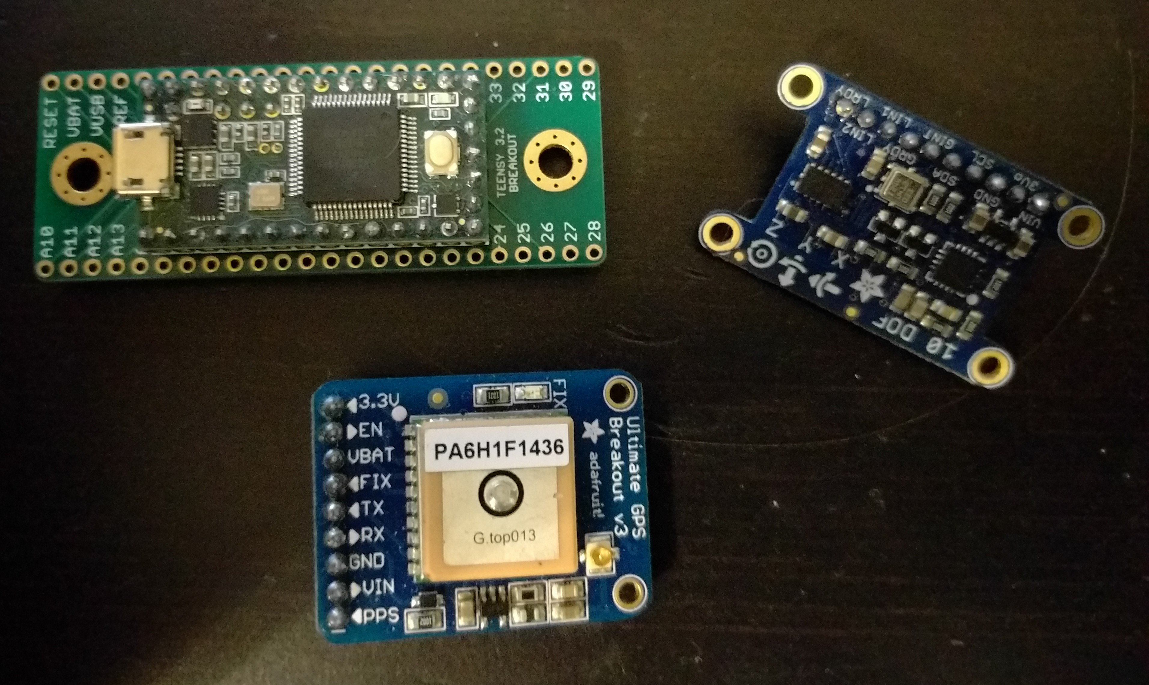
I’m also planning on adding some new sensors to the setup. I’ve got a 10DOF board from Adafruit laying around, which will allow me to use a magnetometer, accelerometer, gyroscope, and barometer. It communicates via I2C and each device on the board has a unique ID. I actually wrote drivers for this board myself in Python a while ago – the should be available on my Github. I have a GPS module that I’d also like to give a try – it will allow me to get velocity and position data. It communicates over a UART connection.
I set about making a new housing for this configuration in Solidworks. I’m planning on only using one CAT5 cable (8 conductors) to bring power, MOSFET PWM signals, and a 3.3v reference voltage back to the rear module.
I do have a few problems/questions I need to work out – for instance – will the GPS be able to get a reliable lock from this position, or do I need an external antenna? How about easy firmware updates? Do I need to keep both encoders and buttons?
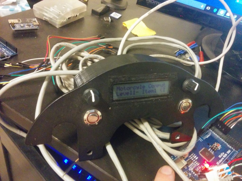
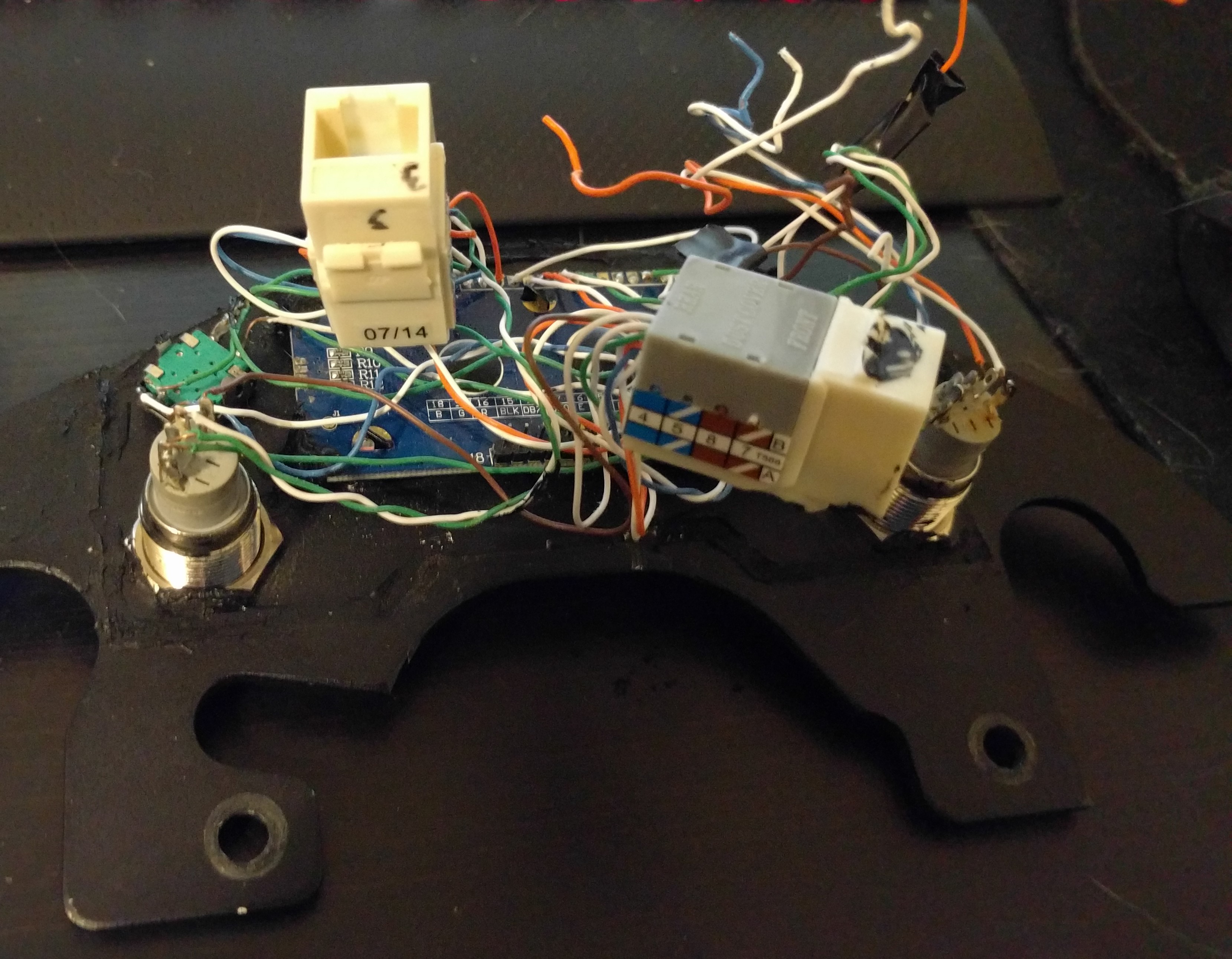
I began to take apart the old setup. Here’s a quick picture after I took off the 3D printed cover and one of the CAT5 connectors.