Author: fillycheezstake

  • Power Monitoring Update

    Power Monitoring Update

    So, after a… while… I finally got around to getting this project together.

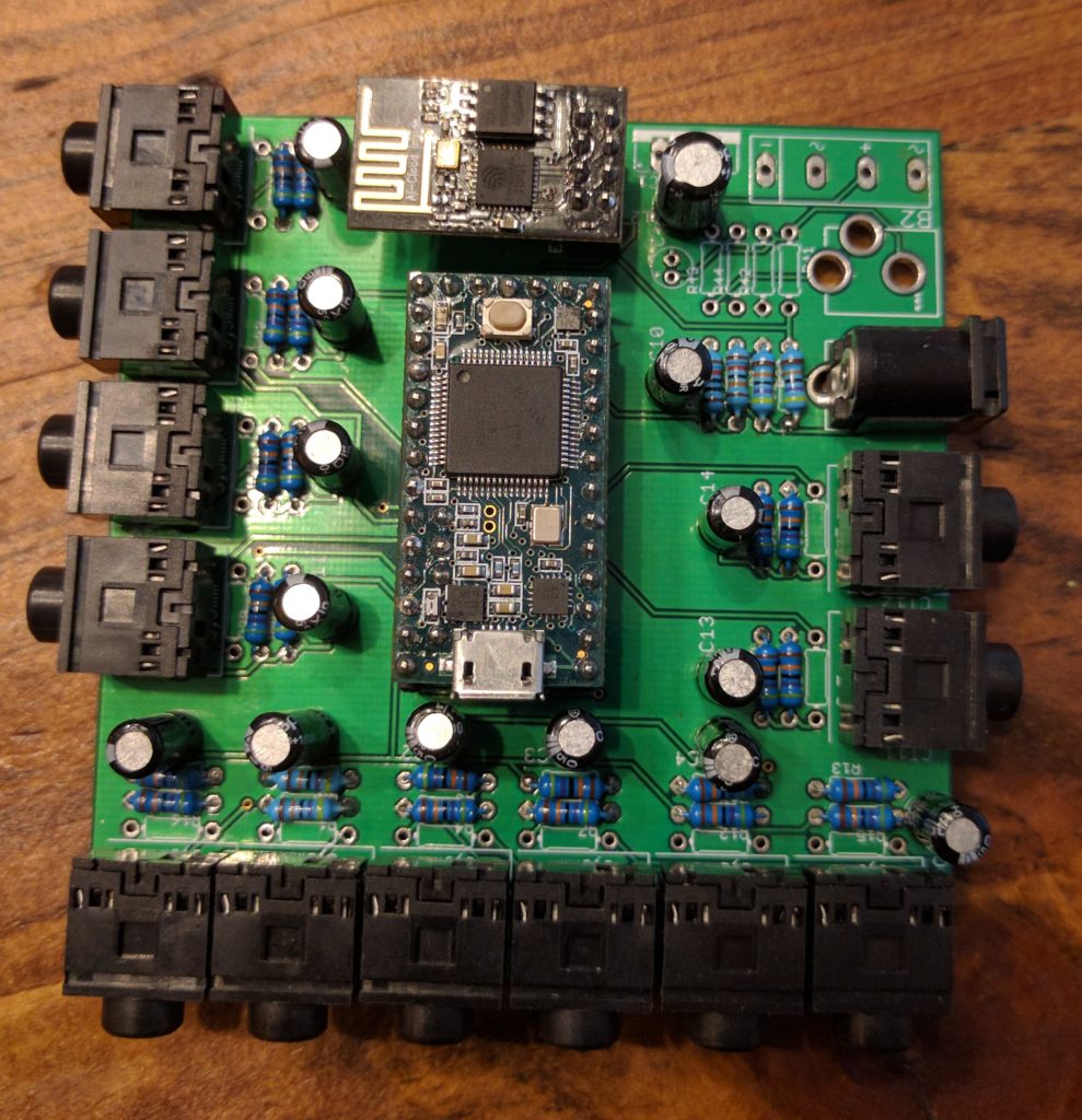
    Below, a quick picture of the completed and populated board. This required quite a bit of soldering, and I discovered a couple of problems during testing (hey, it’s supposed to be  a learning experience!).

    This was fun to solder!

    The Teensy 3.2 and the ESP8266 are removable – they have plugs for all their pins.

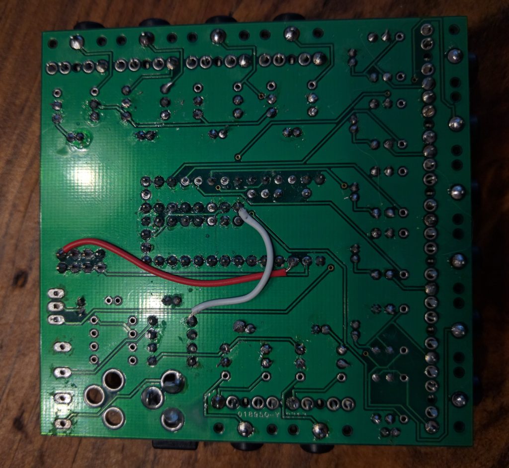
    So the finished board has 12 inputs. The board size is the limit of the free version of EAGLE. On the back is where you’ll see some airwires (aka mistakes).

    Oops.

    Two airwires – one because I forgot to route a pin from the Teensy 3.2 to the ESP8266, and the other because I may have fried one of the input pins on the Teensy trying to get the device powered from AC.

    So when I was designing the board in EAGLE, I knew a lot less about circuit design than I do now (especially AC power). During testing, I discovered that powering the circuit via AC isn’t really that feasible for high currents (the ESP needs >200ma). Not only does the taking power from the AC-AC transformer deform the AC waveform slightly (affecting measurement), you also must use a separate ground for the ADCs.  Oops. Here’s some blog posts describing this –  here and here.

    I haven’t yet uploaded the code to my GitHub account – that’s coming in a future update on the code that supports this project.

  • Power Monitor PCBs arrived today!

    Power Monitor PCBs arrived today!

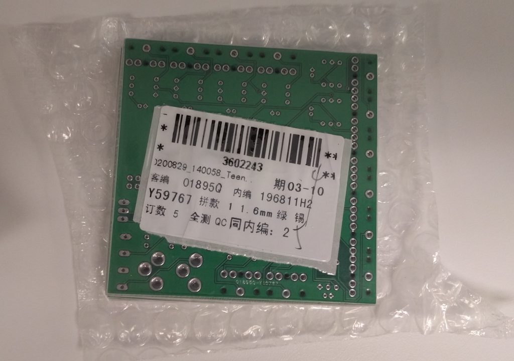
    I got something in the mail today from Seeedstudio!

    Bussin’


    And here they are:

    Packaged well.

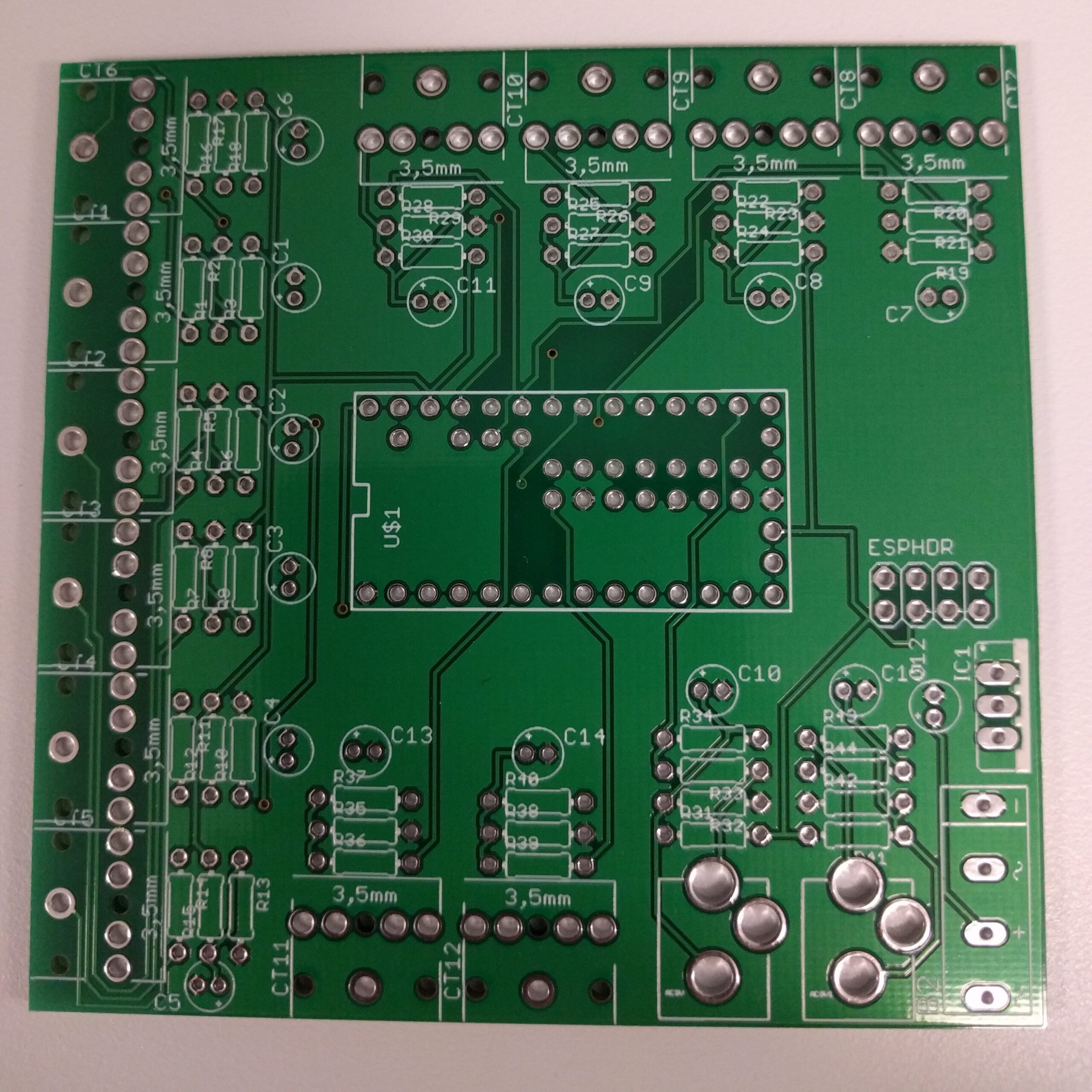
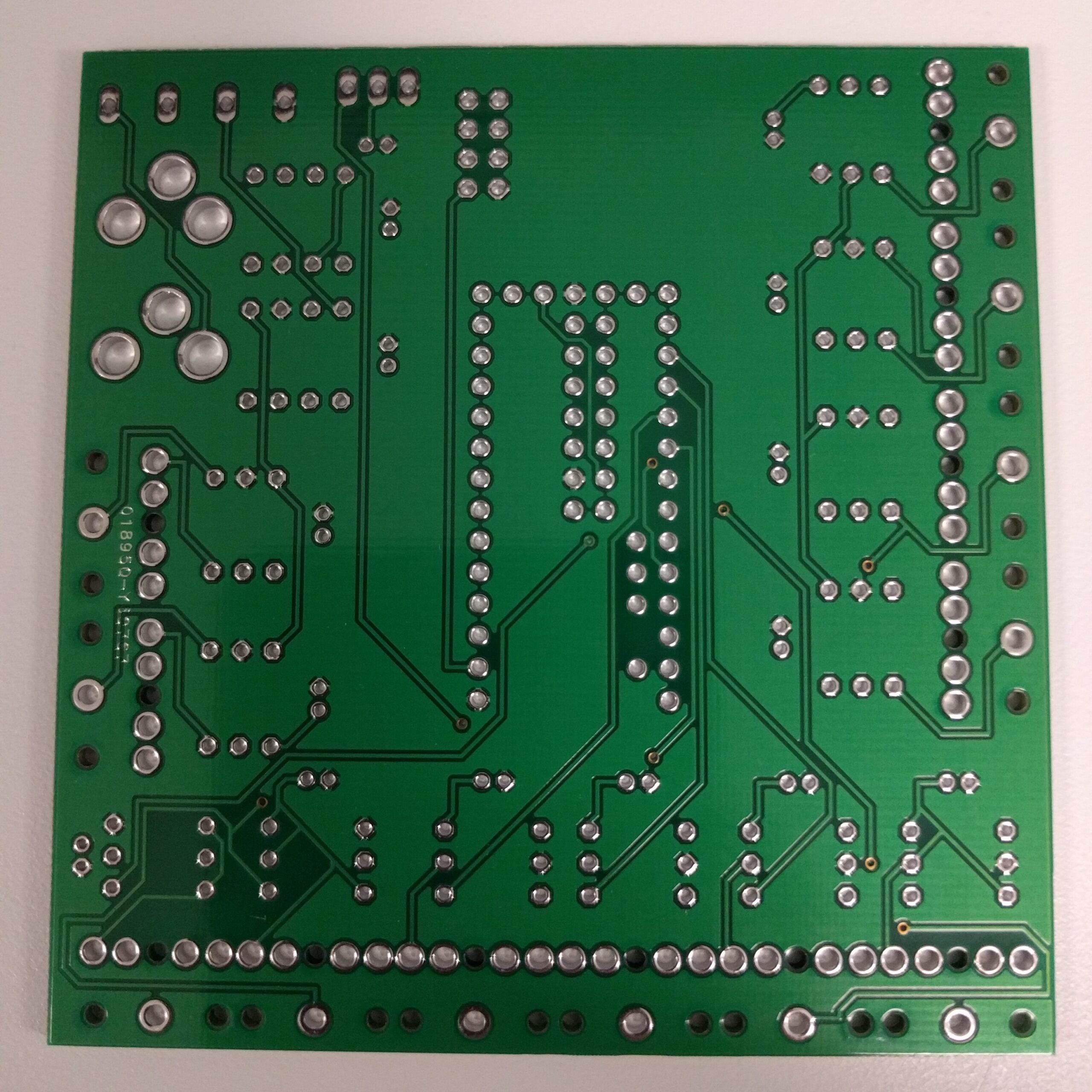
    Here’s some close up shots of both sides:

    I’m very impressed with the quality and value. I only paid $26 for five of these boards! I’ll definitely be ordering from Seeedstudio again in the future. So now the rest of the components have to arrive, and then I’ll be able to begin soldering components to the board.

    The last post describes a bit about the design process.

  • Circuit Design / Personal Energy Monitoring

    Circuit Design / Personal Energy Monitoring

    A while ago, I stumbled upon this great organization: OpenEnergyMonitor. They’re doing a lot of things right!

    Anyway, they prompted me to attempt to create a derivative of their EmonShield TX. I loved the idea, but I wasn’t sold on the RF nature that needed a base station. Since it’s easy to provide WiFi connectivity to an Arduino with the venerable ESP8266, why not make it so? Also the number of circuits (four) wasn’t exactly calling my name. I wanted the ability to do more.

    So.

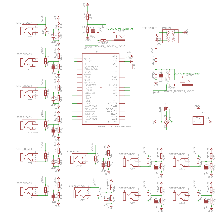
    For non-intrusive current monitoring, current clamps are great. They’re simple current transformers – they themselves are coils of wire, and the conductor around which the clamp is placed forms the other coil.  Thus two things are achieved – isolation and voltage step-down. However, without a burden load, transformers can be dangerous – they build up potential until they reach their insulation’s break-down voltage and fail (sometimes dangerously). So to use these, you MUST have in place a burden resistor, before clamping around a current carrying wire. OpenEnergyMonitor provides a great circuit diagram describing how to both limit the peak voltage, and bias it to remove negative potential (for measurement reasons).  The burden resistor must also be matched so the peak voltage produced by the CT doesn’t saturate or exceed the limits of the device used to measure it.

    Once the CT output is biased and limited to the correct voltage by the burden resistor, it’s ready for measurement by an Analog-to-digital converter.

    To measure voltage, you can simply use a 9VAC transformer to provide a voltage signal (you can also use it to power the contraption). It just takes a bit of biasing and dividing, similar to the CT sensors. Again, OpenEnergyMonitor has diagrams here.  If you wanted to measure both phases of common residential service, you’d need two, and thus two ADC inputs on the measurement device.

    In the US, to measure a 120v device, you need 1 CT sensor and 1 ADC input. However, to measure a 240v device, you must measure both phases and add them together. So each 240v device requires two ADC inputs.

    Now that we have low voltage analog signals, how to we read them? Arduino time! or… not.

    An Arduino Uno has 6 ADC inputs. Not enough for me.

    An Arduino Mega has 16 ADC inputs, but is rather large, and there are many reports of being unable to power the hungry ESP8266. Again, out.

    The Teensy 3.2 board has many more features and ADC inputs in a much smaller package. I use the same board in my revamped Motorcycle Computer project. Its 3.3v regulator can also support the ESP8266’s power requirements. Bingo.

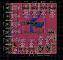
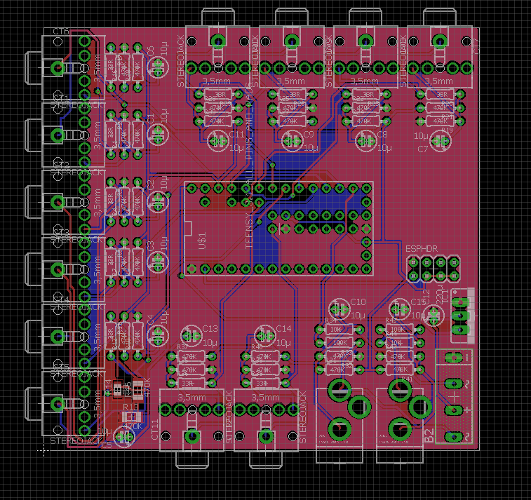
    Now, for the board. I’ve been using EAGLE 7.5 to learn and play around with circuit design. Since this circuit doesn’t have any high speed signals (only 60hz AC), I don’t need to worry much path impedance or other factors in design.  Here’s what I was able to come up with:

    The board layout. I experimented with some surface mount components in the bottom left, but the rest of the components are all through hole.

    And now that I’ve got it designed, I sent it away for manufacturing. I used SeeedStudio for my first ever self-designed PCB creation.  The next update will likely be when I get these in the mail. I’ll make sure to note the turnaround time as well.

  • Thermostat datalogging reboot/major update

    I had a post a while ago talking about how I log the thermostat data from a couple of thermostats located at my parents home.

    Well, take a look at the new thermostat.philipahlers.com!

    This URL actually points to a separate Raspberry Pi (an older Model B) than the one that this site runs on.

    I’ve updated the UI & added some stats calculations. What other stats could be useful for thermostats? I’ve thought of:

    • Average deltaT
    • Average daily temperature
    • Number of cycles

    I’m no pro with nice looking web design or CSS, but I know enough to be dangerous. Also working to have the CSS reside in it’s own external file – right now there’s some in supporting php files, as well as inline in the HTML. I need to work on my coding style!

    The code is located here, as a GitHub repo.

    See any bugs? (I’m working to fix a security issue).

  • Motorcycle Computer: The Screen Module

    Motorcycle Computer: The Screen Module

    I recently found some pictures of construction that I thought I lost, so I’ll be able to do a simple breakdown of the components.

    First – this shelf from AdventureTech, LLC.  Here’s the link to the product page. They’ll even cut holes in it for you, although I cut my own.

    From AdventureTech, LLC
    Image is from AdventureTech, LLC

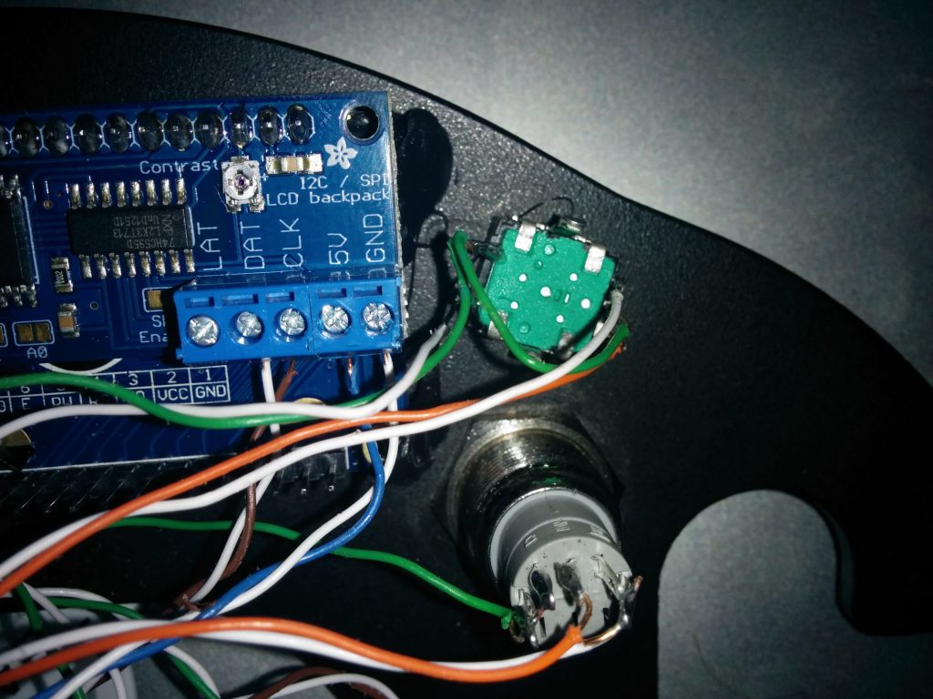
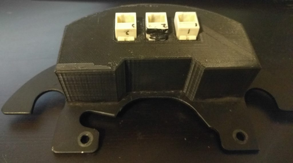
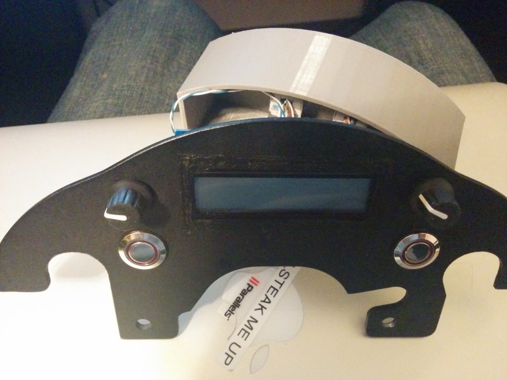
    Once I had the shelf – it’s just a nice powder coated piece of aluminum – I cut out a rectangle for the LCD, and drilled holes for the buttons and rotary encoders I planned to use. Then I soldered wires to all the terminals I’d need – and then routed them to Cat5e jacks, so the actual computing power would be somewhere else on the bike.

    Part of this meant I’d need something to keep the electronics safe and hopefully dry. I modeled a cover in SolidWorks and used a Makerbot Replicator 2 to 3D print a cover. The SolidWorks file is here. I used Black Permatex RTV to seal any openings.

    As stated in another post (this one) I needed to remove I2C from the equation, so that I2C backpack was later removed.

    Here’s a quick parts list:

    • 2x Rotary Encoder – Link
    • 2x LED Button – Link
    • 1x LCD – Link
    • 3x Cat5e Jacks
    • Suzuki V-Strom Shelf (AdventureTech, LLC) – Link
    • 3D Printed Cover
    • Black RTV
  • Motorcycle Computer, Try Number 1

    Motorcycle Computer, Try Number 1

    If you check out the post Heated Jacked PWM Controller, you’ll notice that while I’ve figured out the electronics behind this, I’d yet to figure out the logistics behind a computerized controller.

    The original plan used a Raspberry Pi A+, and also used a Adafruit LCD I2C Backpack. This actually made it to a few test rides on the bike.  It worked! Well, sometimes…

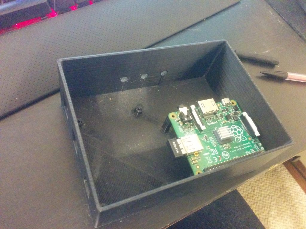
    Short story – This box sat under my seat and housed the Raspberry Pi, MOSFETs, and power supply. This is after I disassembled the first failed attempt.

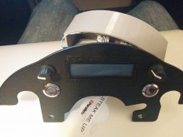
    This unit mounts to my handlebars (and this pic actually has some testing going on).

    Originally, I wanted to control the box using as few wires as possible – the screen takes six (not counting the backlight colors), and each encoder needs two, each button needs one, and buttons need ground. The I2C backpack made controlling the screen possible with only two wires, so I was able to get it down to <16 conductors, or two Cat5e cables.

    BUT – read anything about I2C (which I failed to do) – and you’ll realize a shortcoming.  It’s extremely susceptible to any magnetic or electrical interference. It’s really designed for chips residing on the same PCB.

    So the end result of the Raspberry Pi based system: it worked only when the bike was off. No kidding – without the bike on, there was no interference on the I2C lines, and the screen worked perfectly. I even had a little screen configured to graphically represent the setting of the jacket. The MOSFET worked great, and so did the rotary encoders. For a peek at that old code, see my github repository.

    If the I2C line started seeing errors and missing commands, the screen would display gibberish. Unfortunately, that was really anytime the bike was running. Turns out, metal spinning, fuel pumps pumping, and high-voltage spark plugs firing doesn’t make it a good environment for sensitive protocols like I2C (that’s why things like CAN bus exist). These I2C errors would then make my program hang.  I could have coded some I2C refreshes in, but it doesn’t solve the root cause.

    Back to the drawing board – for a hardware update.

  • Heated Jacket PWM Controller

    Along with owning a fuel-injected motorcycle comes rapid cold-weather starts, as the bike’s fuel mapping takes into account ambient temperature and other environmental factors.  Carbureted engines have lacked this auto-adjusting ability, even with the advent of electric chokes.  And with these nice, smooth cold weather starts – I don’t ever want to stop riding my motorcycle!

    So I recently purchased Gerbing heated jacket liner.  You can buy a controller from Gerbing for ~100 bucks.  But I wanted to do something a little more DIY.  If you did this right, you could build your own heattroller (as they’re called) for around ~15 bucks (555 timer, MOSFET, resistors/capacitors, wiring, but more on my build).

    Essentially, we need a way to switch the jacket on and off in varying degrees, depending on how hot we want the jacket. Why not use a variable resistor, you say? Stay tuned for a lesson on resistance and power. Switching something on and off is much more efficient.

    Enter PWM, or Pulse Width Modulation.  Some may have heard of this technology to dim LEDs, vary the speed of electric motors, or control servos in RC applications.  Essentially, a square wave is generated.  If you don’t know what a square wave looks like, see the Wiki page.  This square wave can be generated at any frequency.  Now, if the square wave spends half it’s time at max amplitude and the other half at zero potential, the duty cycle is 50%.  The longer the square wave is at max amplitude, the higher the duty cycle.  So that’s how we’ll control the on-off action of the jacket current – by increasing or decreasing the duty cycle.

    Choosing a frequency, however is interesting.  For a heated jacket, which has a lot of ‘thermal inertia’ or what I like to call it–in that it doesn’t heat up or cool down super quickly (Gerbing says it takes 4 seconds to reach max temperature) our frequency for the PWM can be fairly low.  I’m using 1 Hz.  Other devices, like LEDs, need to be driven at a much higher frequency because they don’t have any ‘inertia’ (not super sure what word to use here).  Why make it low?  Our later discussion of MOSFETs – switching losses.  Read about it here.

    But we have another problem – what can I generate the PWM signal with?  A 555-timer can be used as an astable oscillator that generates a PWM signal, with the same amplitude of what the 555 timer is powered with.  But a 555 timer can only sink about 200ma of current.  The Gerbing heated jacket liner is rated at 12v and 6.9A.  So we need a sort of relay, or switch to do the actual on-off, and a PWM signal source.

    For my motorcycle, I’m attempting to build a trip computer / recorder out of a Raspberry Pi.  The Raspberry Pi has GPIO pins which can be used to generate a PWM signal at any frequency or duty cycle.  I won’t have to fabricate a 555 circuit!  But we still will need a high-current switch.  A transistor, MOSFET, or even a relay could work at these slow PWM frequencies.  I wanted a solid state option, so I looked around for a MOSFET.

    Laying around in my electronics bin, I had a few of these:  BUZ91A.  Protip:  don’t ever buy these.  I tried to use one, and it promptly got so hot it nearly destroyed itself.  Why?  Take a look at the datasheet – the Rds(on) is .9 ohms!  That’s a lot.  And we know that

    P = V * I and V = I * R

    Thus,

    P = I * R * I

    P = I2 * R

    What does this mean?  Our jacket drawing 6.9 Amps would mean the MOSFET would have to dissipate nearly 43 Watts.  Not what you would call efficient or safe.  That would take a fairly large heatsink.  So after some looking around, I decided to purchase a few of these.  The Rds(on) is only .028 ohms.  Now, the MOSFET only should need to dissipate less than 1.4 Watts.  That’s a bit of an improvement, I’d say.  It probably won’t even need a heatsink with that load on it – especially since heated jackets are only used when the ambient temperature is <50degF.

    For more info, you can read the Wiki page on PWM.

    Or read up on some Ohms law (this site was awesome in college)!

  • LED Taillight: More

    So, I’ve been busy.  New job, new place to live, and have had a few other priorities.  Since my last post, I’ve sold my 2003 Honda Shadow Spirit.  It was my first bike, and I was sad to see it go.  But 3 bikes seemed one too many.  (If you ask my girlfriend, I still have 2 too many).

    Anyway — back to the LED Taillight project.

    I have finished the project now.  Since I was in between phones — some steps don’t have pictures.

    Since the last post, I redesigned how I laid out the LEDs.

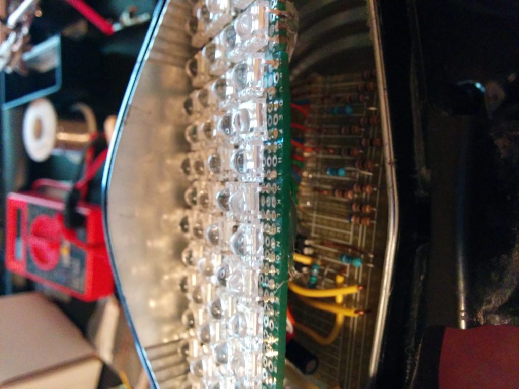
    There are a total of 70 LEDs in this array.  The specs on these red LEDs can be found here. Each puts out 10 lumens when given the proper current and voltage.  This produces 700 lumens if all are on.  In contrast, 21+5W of the old incandescent puts out around ~450 I believe.  The array of 70 LEDs was wired as 14 parallel sets of 5 in series.  Each set of 5 in series has its own resistor.  I chose 68 ohm resistors.  This site came in handy during the planning stages so I didn’t have to to the math.

    So I wired all the LEDs to a separate project breadboard where I could place my resistors, and more importantly, my flashing circuit.

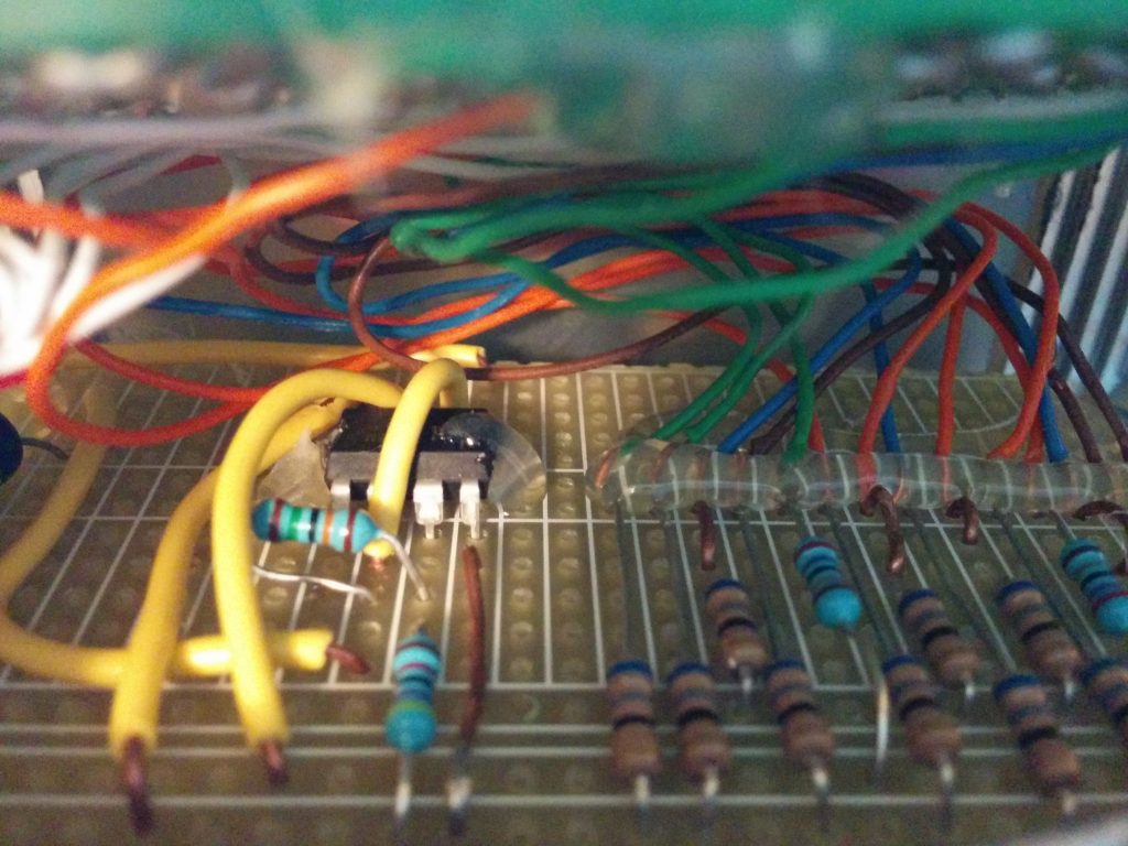
    After this was done, I wanted the bottom row of LEDs to flash during braking.  I’ve seen my friend’s BMW 650GS have this flashing stock from the factory, and I liked it.  So I designed an astable 555 timer circuit that flashed at the frequency I wanted.  There are numerous calculators and circuit diagrams online for setting up your 555 timer to oscillate at the frequency you want.  HOWEVER – when the 555 timer is used to provide the current (you can either sink current into the 555 timer output, or have it produce it)  it has a voltage drop of about ~2 volts.  In addition, it can only sink / provide about 200ma of current reliably before it starts to heat up.  This means the resistors I used on the flashing LEDs had to be less if they were to be the same brightness.

    And a picture of the little 555 timer circuit:

    Hot glue was nice to hold things in place during soldering, and provides a good insulator / way to prevent wires from touching.

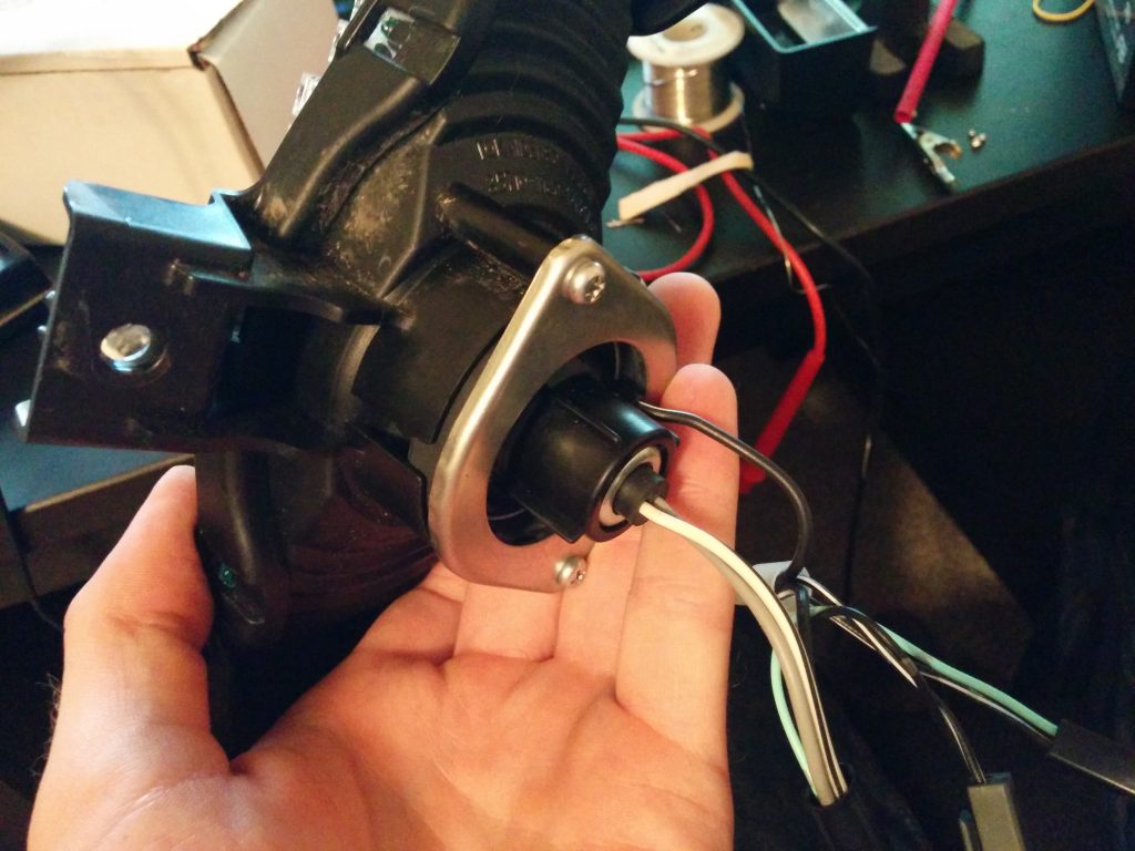
    Oh yeah, how did I get away with not cutting/splicing any wires?  I simply broke the old incandescent light, removed all the glass, and soldered leads onto the bulbs filament stand-offs.  I covered them in heat shrink tubing and made sure bending wouldn’t occur and break these.  It worked great, however ratchet.

    After this was all in place, I once again used the heat gun to soften the glue holding the two halves of the light housing back together.

    Sorry I didn’t have more pictures of the LED blinkers, but they’re the same principle.  I used amber lights instead of red, and had to get a relay that flashed at the proper rate from ebay.  It was only 13 bucks shipped!

  • Breaking Down

    Breaking Down

    Friday, July 25, 2014.

    I had stayed at the office till late, about ~9pm, and it was dark. I went to go home, tossed on my riding gear, and started my 1992 Honda Nighthawk. The headlight wasn’t working.

    What was interesting is that neither the normal or the high-beam was working.  Since I know that H4 bulbs (a common headlight bulb type) have two separate filaments, it should only lose low beam or high beam at once.  Losing both at once is rare.

    So to get home, I had to be rescued with some tools and wires.  I simply ‘hot-wired’ the headlight buy running a wire right to the battery.  I know it’s unsafe being unfused and all, but I had to make it home.

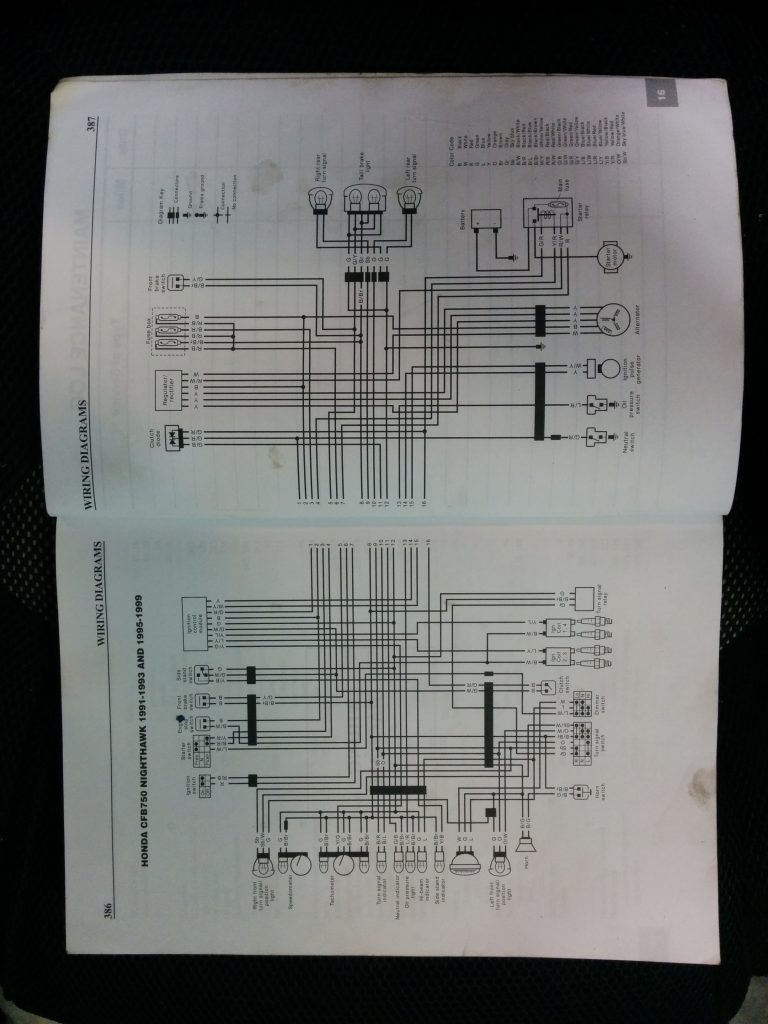
    After taking a look at the wiring diagram below, I narrowed it down to a few things.

    From my workshop manual for the bike.

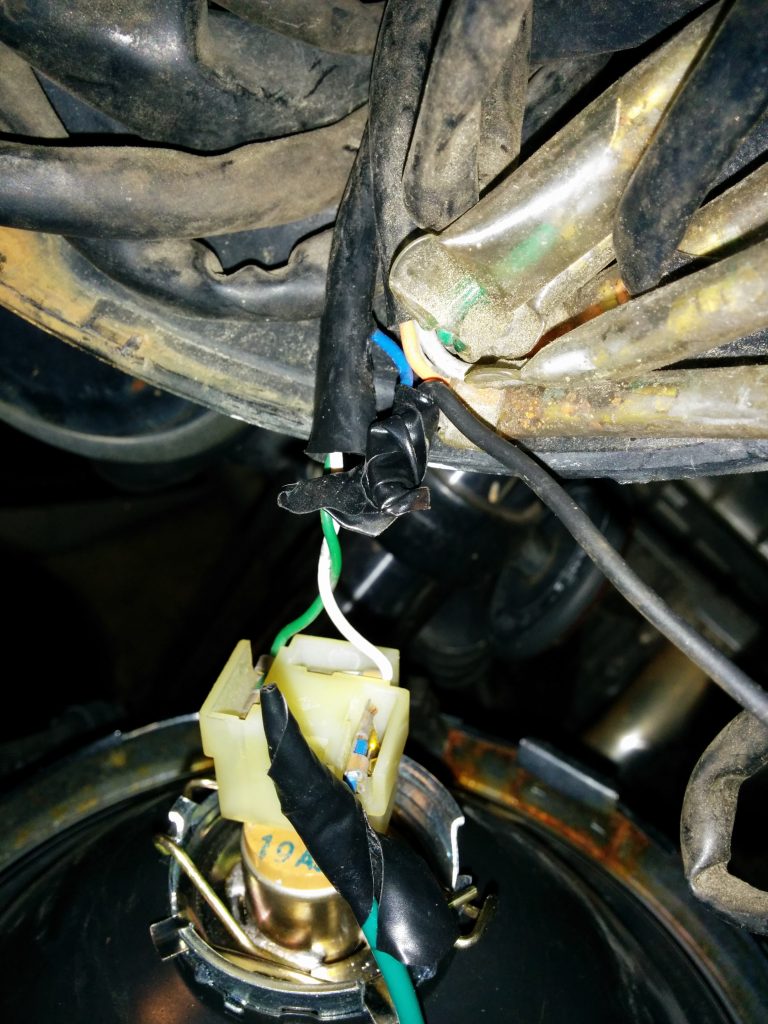
    If you blow up the picture (I think you should be able to) you can trace the headlight to the dimmer switch (on the left handlebar) and curiously, the starter button (on the right handlebar).  I knew the bulb was good, and tested wiring between the switches and the headlight. The wires were good, although at some point, someone had sliced into the headlamp wire, below.

    So my best guess for the reason for this was a modulator (a dohickey that basically flashes the headlight, to make it supposedly easier to see).  I fixed this by correctly splicing the wires using solder and heat shrink. Before, someone had just twisted the wires together and wrapped them with duct tape.

    The solution ended up being that starter button – it needed some serious cleaning and a bit of grease.

  • Thermostat Logging / Datamining

    So, I’m not so fancy as to have a Nest thermostat or anything, but I do have access to two WiFi enabled thermostats that have a closed-source app for iOS and Android, and a closed source web app. These tools are nice, but lack a lot of useful features. The company who made these did, however, release a public API which is pretty useful. Unfortunately, the thermostats never really caught on in the developer or the consumer world. There are a few people online who do work on them, and I’ve managed to figure a few things out.

    The thermostats I have access to are marketed under either Radio Thermostat CT50 or Filtrete 3M-50.

    The API has a few versions (I haven’t been able to tell a significant difference) that is published here.

    –Update-– That link is now broken – Radio Thermostat have since taken down their API documentation. Here’s a copy of the API documentation.

    The API works great–but the thermostats do take a bit of time to respond to any GET or POST actions. For instance, my python script that polls them takes about 5 seconds to come back with any data.

    So, I set up a mySQL database, user, and table for my project.  Easy enough. Then I wrote a script in Python to grab a few bits of information from the thermostat, like current temperature, commanded temperature, fan state, and thermostat state. Each thermostat has the ability to store a name for itself, so that’s in there too.

    But I wanted the ability to compare my data to outside temperature (ie, get a DeltaT) in order to see the outside temperature’s effect on the inside.  So, I looked around, and remembered some work I’d done with Weather Underground.  They have a free API that allows me up to 10 calls a minute!  I’d only use about 1 every 5 minutes.  So I signed up for that and read through the documentation and was able to get what I wanted and much, much more.  That API can be found here.

    My simple python script to grab this:

    #!usr/bin/env python

    import radiotherm
    #much thanks to Michael Hrivnak <mhrivnak@hrivnak.org> for his simple library!
    #i wrote a similar thing in java when i did this project version 1, this is way easier.
    #plus I learned mySQL, Python, php, and other stuff during this project. vs my old stupid method
    import MySQLdb
    import time
    import urllib2
    import json #jaaaaaaaaason

    #this small script grabs the temp for where the thermostats are located:raleigh, nc
    #weather underground key:131beb0f35b8df99
    #wunderground gives nice json! examples can be found on their website. most of this script is directly from their website.
    f = urllib2.urlopen('http://api.wunderground.com/api/******************/geolookup/conditions/q/NC/Raleigh.json')
    json_string = f.read()
    parsed_json = json.loads(json_string)
    temp_f = parsed_json['current_observation']['temp_f']
    f.close()

    #logging into the mysql server
    #the ol classic pw!
    db = MySQLdb.connect(host="localhost",
    user="monitor",
    passwd="*************",
    db="Temps")

    cur = db.cursor() #setting the cursor for the sql database

    #start to use this nice library.
    def getinfo(ip):
    tstat = radiotherm.get_thermostat(ip)
    #tstat.temp & dicts use dicts as output.

    temp = tstat.temp['raw'] #this grabs the raw value of temp from the therm and puts into a float
    FanState = tstat.fstate['raw'] #this grabs the raw value of fan on or off
    ThermState = tstat.tstate['raw'] #this grabs raw value of thermostat commanding cool, heat, off
    tname = tstat.name['raw'] #name of thermostat given by the radio thermostat company
    comm = tstat.t_cool['raw'] #commanded temp, not sure the difference b/w t_cool and it_cool
    return {'temp':temp, 'FanState':FanState ,'ThermState':ThermState,'ThermName':tname,'comm':comm}

    def writeinfo(dict):
    try:
    cur.execute("INSERT INTO tempdat VALUES (CURDATE(),NOW(),%s,%s,%s,%s,%s,%s)", (dict['ThermName'],dict['temp'],dict['ThermState'],dict['FanState'],temp_f,dict['comm'])

    db.commit()
    print "nData Committed!" , dict['ThermName']except:
    print "Error in committing, rolling back!"
    db.rollback()

    #while 1: #used to have it run in a while loop, cron is waaaaaaaay better.

    #these IPs are internal LAN addresses that won't change. I've set them up as static in my router.
    #The database entries will automatically know which is downstairs and upstairs
    writeinfo(getinfo('192.168.0.13'))
    writeinfo(getinfo('192.168.0.16'))

    #this was for tshooting/seeing the database grow, too big now! =P

    #cur.execute ("SELECT * FROM tempdat")

    #print "nDate Time Zone Temperature ThermState FanState Outside Commanded"
    #print "============================================================================================"

    #for reading in cur.fetchall():
    #print str(reading[0])+" "+str(reading[1])+" "+
    # reading[2]+" "+str(reading[3])+" "+str(reading[4])+" "+ str(reading[5])+" "+str(reading[6])+" "+str(reading[7])

    #time.sleep(300) #more for the old dumb while loop

    db.close()