Category: Motorcycle

  • Motorcycle Computer Revisit

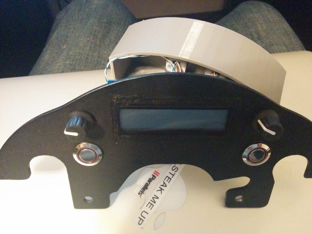
    About a year ago, I made this motorcycle computer that mounts to the dash of my 2012 V-Strom 650. It controlled my heated jacket and my heated grips.

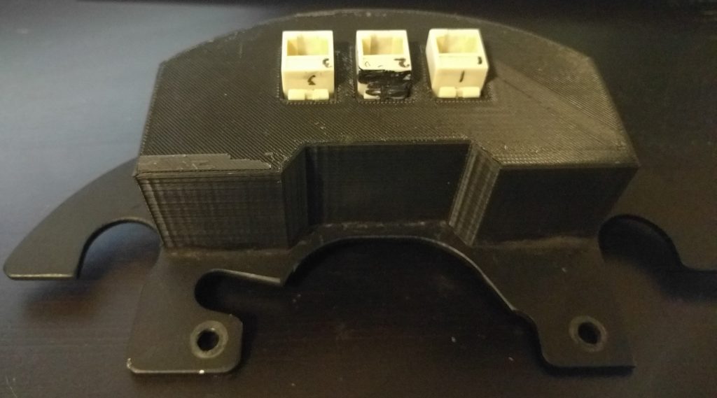
    I have access to a 3D printer at work, so I modeled some housings in Solidworks and printed them out. It’s awesome – 3D printers make prototyping and hobby projects really easy! The housing is held in place to the anodized aluminum plate with standard automotive RTV.
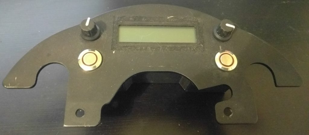
    Front
    Rear

    The below box housed the ‘brains’ and resided under the seat. This left the signal lines to the screen and rotary encoders exposed to a LOT of interference. My new plan is to move the Teensy 3.2 into the same housing as the screen, and make a much smaller box to house only the MOSFETs, 12v-5v DC-DC converter, and a logic-level converter to ensure the MOSFETs see a signal that is above their minimum spec to ensure the gate is pulled high.
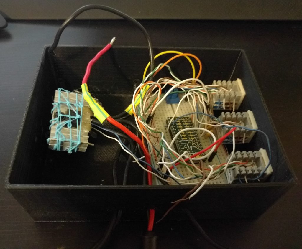
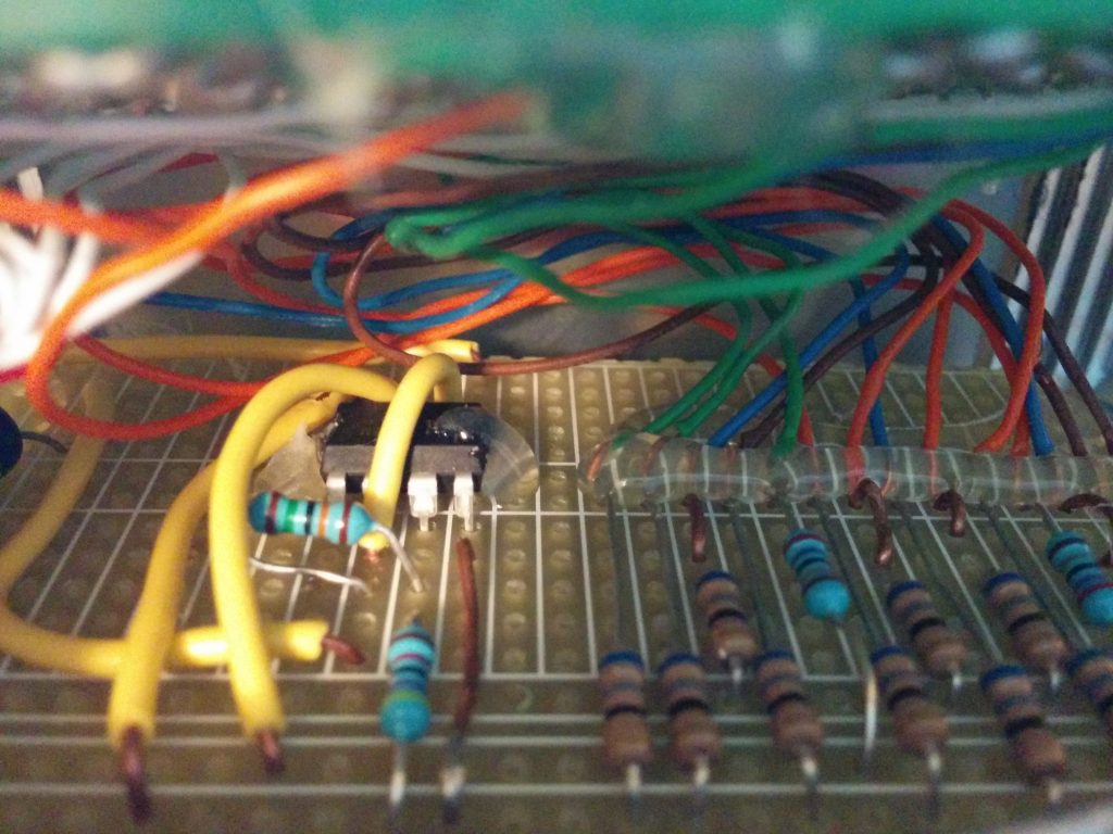
    Spaghetti.

    This setup has been on the motorcycle for about a year – and no real ill effects were noticed. I never once had to fix anything. The code could use a bit of work to make the interface a more intuitive, but that’s also part of this revisit.

    I’m also planning on adding some new sensors to the setup. I’ve got a 10DOF board from Adafruit laying around, which will allow me to use a magnetometer, accelerometer, gyroscope, and barometer. It communicates via I2C and each device on the board has a unique ID. I actually wrote drivers for this board myself in Python a while ago – the should be available on my Github. I have a GPS module that I’d also like to give a try – it will allow me to get velocity and position data. It communicates over a UART connection.
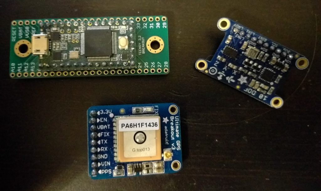
    GPS, 6DOF Sensor, Teensy 3.2

    I set about making a new housing for this configuration in Solidworks. I’m planning on only using one CAT5 cable (8 conductors) to bring power, MOSFET PWM signals, and a 3.3v reference voltage back to the rear module.

    I do have a few problems/questions I need to work out – for instance – will the GPS be able to get a reliable lock from this position, or do I need an external antenna? How about easy firmware updates? Do I need to keep both encoders and buttons?
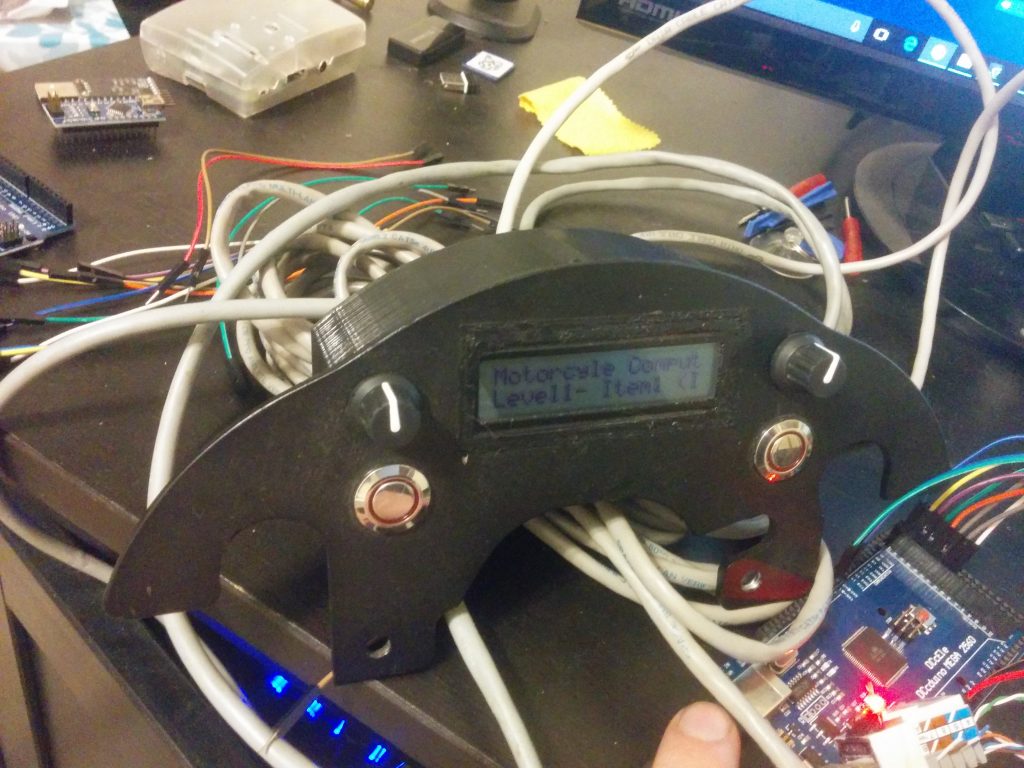
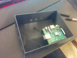
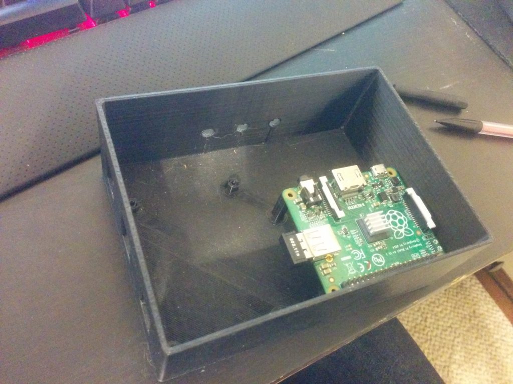
    I began to take apart the old setup. Here’s a quick picture after I took off the 3D printed cover and one of the CAT5 connectors.
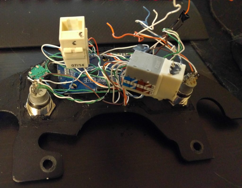
    More Spaghetti.
  • Motorcycle Computer: The Screen Module

    Motorcycle Computer: The Screen Module

    I recently found some pictures of construction that I thought I lost, so I’ll be able to do a simple breakdown of the components.

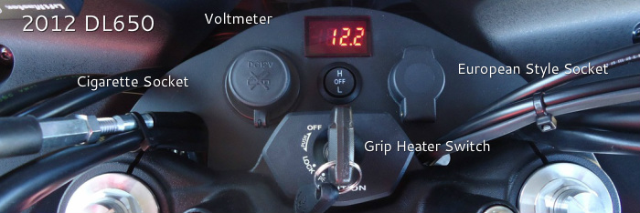
    First – this shelf from AdventureTech, LLC.  Here’s the link to the product page. They’ll even cut holes in it for you, although I cut my own.

    From AdventureTech, LLC
    Image is from AdventureTech, LLC

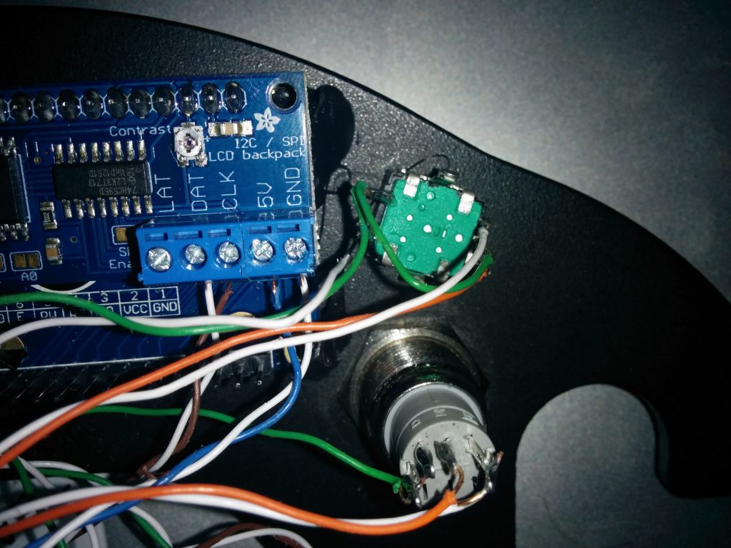
    Once I had the shelf – it’s just a nice powder coated piece of aluminum – I cut out a rectangle for the LCD, and drilled holes for the buttons and rotary encoders I planned to use. Then I soldered wires to all the terminals I’d need – and then routed them to Cat5e jacks, so the actual computing power would be somewhere else on the bike.

    Part of this meant I’d need something to keep the electronics safe and hopefully dry. I modeled a cover in SolidWorks and used a Makerbot Replicator 2 to 3D print a cover. The SolidWorks file is here. I used Black Permatex RTV to seal any openings.

    As stated in another post (this one) I needed to remove I2C from the equation, so that I2C backpack was later removed.

    Here’s a quick parts list:

    • 2x Rotary Encoder – Link
    • 2x LED Button – Link
    • 1x LCD – Link
    • 3x Cat5e Jacks
    • Suzuki V-Strom Shelf (AdventureTech, LLC) – Link
    • 3D Printed Cover
    • Black RTV
  • Motorcycle Computer, Try Number 1

    Motorcycle Computer, Try Number 1

    If you check out the post Heated Jacked PWM Controller, you’ll notice that while I’ve figured out the electronics behind this, I’d yet to figure out the logistics behind a computerized controller.

    The original plan used a Raspberry Pi A+, and also used a Adafruit LCD I2C Backpack. This actually made it to a few test rides on the bike.  It worked! Well, sometimes…

    Short story – This box sat under my seat and housed the Raspberry Pi, MOSFETs, and power supply. This is after I disassembled the first failed attempt.

    This unit mounts to my handlebars (and this pic actually has some testing going on).

    Originally, I wanted to control the box using as few wires as possible – the screen takes six (not counting the backlight colors), and each encoder needs two, each button needs one, and buttons need ground. The I2C backpack made controlling the screen possible with only two wires, so I was able to get it down to <16 conductors, or two Cat5e cables.

    BUT – read anything about I2C (which I failed to do) – and you’ll realize a shortcoming.  It’s extremely susceptible to any magnetic or electrical interference. It’s really designed for chips residing on the same PCB.

    So the end result of the Raspberry Pi based system: it worked only when the bike was off. No kidding – without the bike on, there was no interference on the I2C lines, and the screen worked perfectly. I even had a little screen configured to graphically represent the setting of the jacket. The MOSFET worked great, and so did the rotary encoders. For a peek at that old code, see my github repository.

    If the I2C line started seeing errors and missing commands, the screen would display gibberish. Unfortunately, that was really anytime the bike was running. Turns out, metal spinning, fuel pumps pumping, and high-voltage spark plugs firing doesn’t make it a good environment for sensitive protocols like I2C (that’s why things like CAN bus exist). These I2C errors would then make my program hang.  I could have coded some I2C refreshes in, but it doesn’t solve the root cause.

    Back to the drawing board – for a hardware update.

  • Heated Jacket PWM Controller

    Along with owning a fuel-injected motorcycle comes rapid cold-weather starts, as the bike’s fuel mapping takes into account ambient temperature and other environmental factors.  Carbureted engines have lacked this auto-adjusting ability, even with the advent of electric chokes.  And with these nice, smooth cold weather starts – I don’t ever want to stop riding my motorcycle!

    So I recently purchased Gerbing heated jacket liner.  You can buy a controller from Gerbing for ~100 bucks.  But I wanted to do something a little more DIY.  If you did this right, you could build your own heattroller (as they’re called) for around ~15 bucks (555 timer, MOSFET, resistors/capacitors, wiring, but more on my build).

    Essentially, we need a way to switch the jacket on and off in varying degrees, depending on how hot we want the jacket. Why not use a variable resistor, you say? Stay tuned for a lesson on resistance and power. Switching something on and off is much more efficient.

    Enter PWM, or Pulse Width Modulation.  Some may have heard of this technology to dim LEDs, vary the speed of electric motors, or control servos in RC applications.  Essentially, a square wave is generated.  If you don’t know what a square wave looks like, see the Wiki page.  This square wave can be generated at any frequency.  Now, if the square wave spends half it’s time at max amplitude and the other half at zero potential, the duty cycle is 50%.  The longer the square wave is at max amplitude, the higher the duty cycle.  So that’s how we’ll control the on-off action of the jacket current – by increasing or decreasing the duty cycle.

    Choosing a frequency, however is interesting.  For a heated jacket, which has a lot of ‘thermal inertia’ or what I like to call it–in that it doesn’t heat up or cool down super quickly (Gerbing says it takes 4 seconds to reach max temperature) our frequency for the PWM can be fairly low.  I’m using 1 Hz.  Other devices, like LEDs, need to be driven at a much higher frequency because they don’t have any ‘inertia’ (not super sure what word to use here).  Why make it low?  Our later discussion of MOSFETs – switching losses.  Read about it here.

    But we have another problem – what can I generate the PWM signal with?  A 555-timer can be used as an astable oscillator that generates a PWM signal, with the same amplitude of what the 555 timer is powered with.  But a 555 timer can only sink about 200ma of current.  The Gerbing heated jacket liner is rated at 12v and 6.9A.  So we need a sort of relay, or switch to do the actual on-off, and a PWM signal source.

    For my motorcycle, I’m attempting to build a trip computer / recorder out of a Raspberry Pi.  The Raspberry Pi has GPIO pins which can be used to generate a PWM signal at any frequency or duty cycle.  I won’t have to fabricate a 555 circuit!  But we still will need a high-current switch.  A transistor, MOSFET, or even a relay could work at these slow PWM frequencies.  I wanted a solid state option, so I looked around for a MOSFET.

    Laying around in my electronics bin, I had a few of these:  BUZ91A.  Protip:  don’t ever buy these.  I tried to use one, and it promptly got so hot it nearly destroyed itself.  Why?  Take a look at the datasheet – the Rds(on) is .9 ohms!  That’s a lot.  And we know that

    P = V * I and V = I * R

    Thus,

    P = I * R * I

    P = I2 * R

    What does this mean?  Our jacket drawing 6.9 Amps would mean the MOSFET would have to dissipate nearly 43 Watts.  Not what you would call efficient or safe.  That would take a fairly large heatsink.  So after some looking around, I decided to purchase a few of these.  The Rds(on) is only .028 ohms.  Now, the MOSFET only should need to dissipate less than 1.4 Watts.  That’s a bit of an improvement, I’d say.  It probably won’t even need a heatsink with that load on it – especially since heated jackets are only used when the ambient temperature is <50degF.

    For more info, you can read the Wiki page on PWM.

    Or read up on some Ohms law (this site was awesome in college)!

  • LED Taillight: More

    So, I’ve been busy.  New job, new place to live, and have had a few other priorities.  Since my last post, I’ve sold my 2003 Honda Shadow Spirit.  It was my first bike, and I was sad to see it go.  But 3 bikes seemed one too many.  (If you ask my girlfriend, I still have 2 too many).

    Anyway — back to the LED Taillight project.

    I have finished the project now.  Since I was in between phones — some steps don’t have pictures.

    Since the last post, I redesigned how I laid out the LEDs.

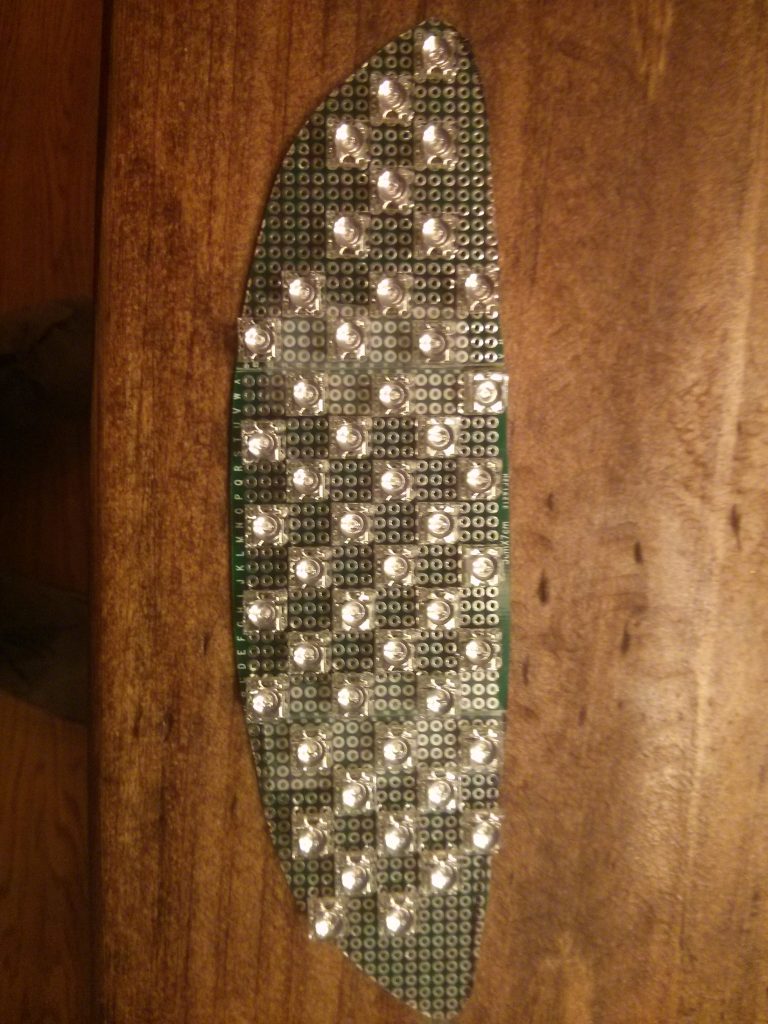
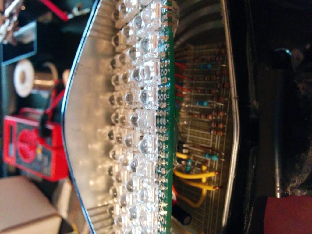
    There are a total of 70 LEDs in this array.  The specs on these red LEDs can be found here. Each puts out 10 lumens when given the proper current and voltage.  This produces 700 lumens if all are on.  In contrast, 21+5W of the old incandescent puts out around ~450 I believe.  The array of 70 LEDs was wired as 14 parallel sets of 5 in series.  Each set of 5 in series has its own resistor.  I chose 68 ohm resistors.  This site came in handy during the planning stages so I didn’t have to to the math.

    So I wired all the LEDs to a separate project breadboard where I could place my resistors, and more importantly, my flashing circuit.

    After this was done, I wanted the bottom row of LEDs to flash during braking.  I’ve seen my friend’s BMW 650GS have this flashing stock from the factory, and I liked it.  So I designed an astable 555 timer circuit that flashed at the frequency I wanted.  There are numerous calculators and circuit diagrams online for setting up your 555 timer to oscillate at the frequency you want.  HOWEVER – when the 555 timer is used to provide the current (you can either sink current into the 555 timer output, or have it produce it)  it has a voltage drop of about ~2 volts.  In addition, it can only sink / provide about 200ma of current reliably before it starts to heat up.  This means the resistors I used on the flashing LEDs had to be less if they were to be the same brightness.

    And a picture of the little 555 timer circuit:

    Hot glue was nice to hold things in place during soldering, and provides a good insulator / way to prevent wires from touching.

    Oh yeah, how did I get away with not cutting/splicing any wires?  I simply broke the old incandescent light, removed all the glass, and soldered leads onto the bulbs filament stand-offs.  I covered them in heat shrink tubing and made sure bending wouldn’t occur and break these.  It worked great, however ratchet.

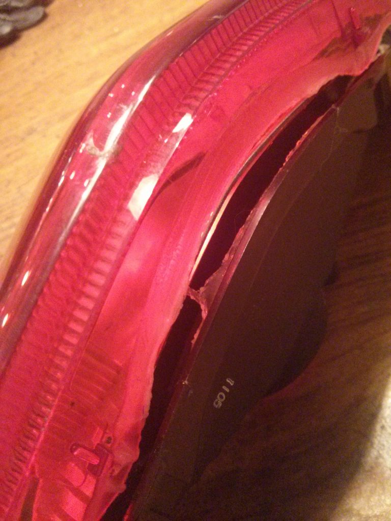
    After this was all in place, I once again used the heat gun to soften the glue holding the two halves of the light housing back together.

    Sorry I didn’t have more pictures of the LED blinkers, but they’re the same principle.  I used amber lights instead of red, and had to get a relay that flashed at the proper rate from ebay.  It was only 13 bucks shipped!

  • Breaking Down

    Breaking Down

    Friday, July 25, 2014.

    I had stayed at the office till late, about ~9pm, and it was dark. I went to go home, tossed on my riding gear, and started my 1992 Honda Nighthawk. The headlight wasn’t working.

    What was interesting is that neither the normal or the high-beam was working.  Since I know that H4 bulbs (a common headlight bulb type) have two separate filaments, it should only lose low beam or high beam at once.  Losing both at once is rare.

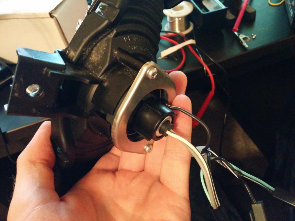
    So to get home, I had to be rescued with some tools and wires.  I simply ‘hot-wired’ the headlight buy running a wire right to the battery.  I know it’s unsafe being unfused and all, but I had to make it home.

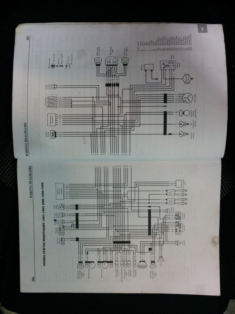
    After taking a look at the wiring diagram below, I narrowed it down to a few things.

    From my workshop manual for the bike.

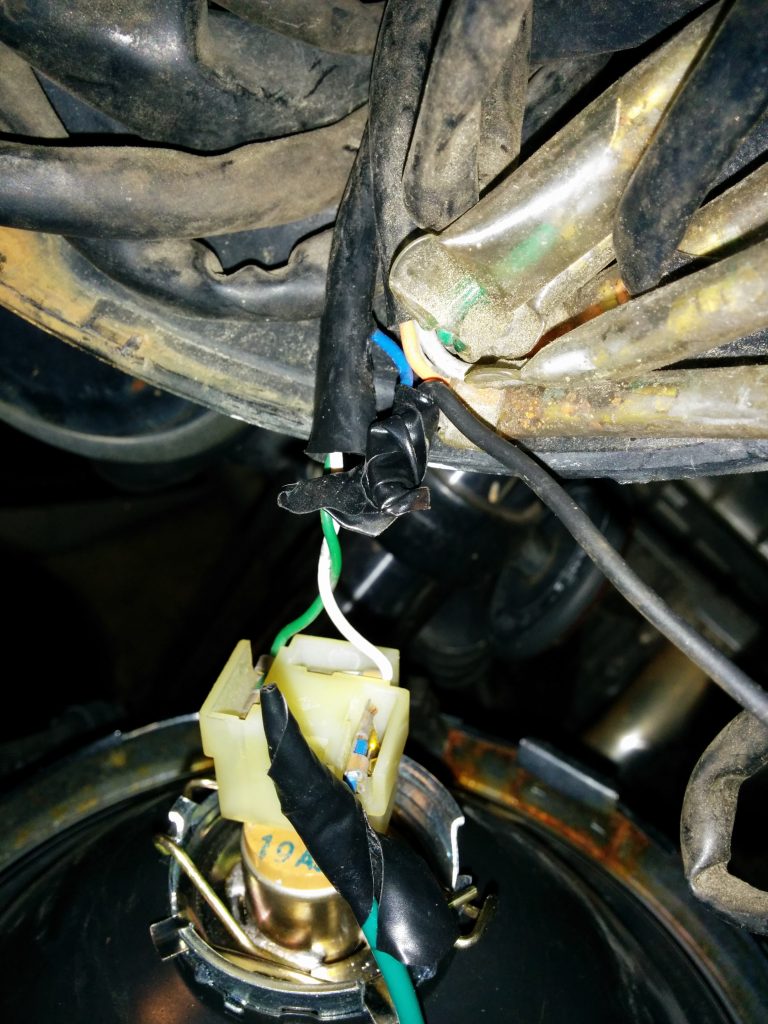
    If you blow up the picture (I think you should be able to) you can trace the headlight to the dimmer switch (on the left handlebar) and curiously, the starter button (on the right handlebar).  I knew the bulb was good, and tested wiring between the switches and the headlight. The wires were good, although at some point, someone had sliced into the headlamp wire, below.

    So my best guess for the reason for this was a modulator (a dohickey that basically flashes the headlight, to make it supposedly easier to see).  I fixed this by correctly splicing the wires using solder and heat shrink. Before, someone had just twisted the wires together and wrapped them with duct tape.

    The solution ended up being that starter button – it needed some serious cleaning and a bit of grease.

  • LED Taillight Project

    LED Taillight Project

    As I stated in a previous post regarding my 2012 Suzuki V-Strom 650,  the lack of LED lighting is disappointing.  For me, LEDs just look cooler, can be seen easier, and don’t have that ‘warm-up’ time that incandescent bulbs have. Some even say that this effect can reduce reaction times.

    So, what would be the best way to light up the entire taillight housing with LED power?  After some research, some people simply drop in a replacement LED bulb.  Since my taillight takes the bulb type 1157, I looked at a few direct drop in LED replacements for the incandescent 1157.

    Nice bulbs, man.
    Huh. (superbrightleds.com)

    But, after reading some on various car and motorcycle forums, it seems that these bulbs are far from ideal–since it’s hard to make an LED with a 360 degree spherical light spread.  All of these types of bulbs attempt to replicate the incandescent by shotgunning, or putting a load of LEDs on the drop-in bulb.  Users reported that the LEDs replacements still don’t appear to fill the entire housing with light.

    So, I decided against buying an off the shelf LED replacement bulb.

    I then stumbled upon a few forums where people had made their own LED arrays, and found www.superbrightleds.com.  I placed an order for a bunch of these guys.  Why red and not white? Well, white LEDs are more expensive, and the taillight lens filters all other wavelengths out – so the white LEDs wouldn’t appear as bright, as most of the wavelengths produced would be filtered out.

    And so, the work begins.

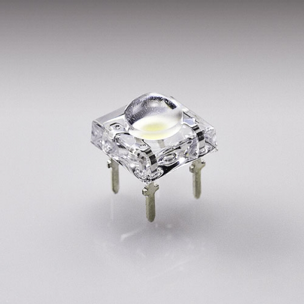
    Red LED (superbrightleds.com)

    That’s one of the LEDs that I ordered.  I ordered 50 of the red.  They have 4 pins–two for each the anode and the cathode.

    Opening it up!

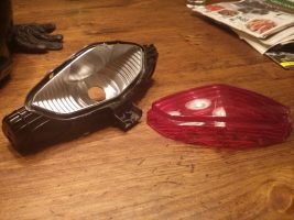
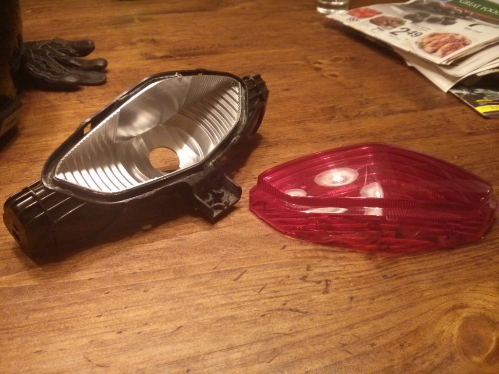
    So I pulled the taillight housing out of the V-Strom.  This meant taking off my sidecase mounts and unbolting a few things and taking out a couple of those plastic ‘Christmas tree’ fasteners.  I used a heat gun to separate the two halves, as they were glued/sealed together.

    Two pieces!

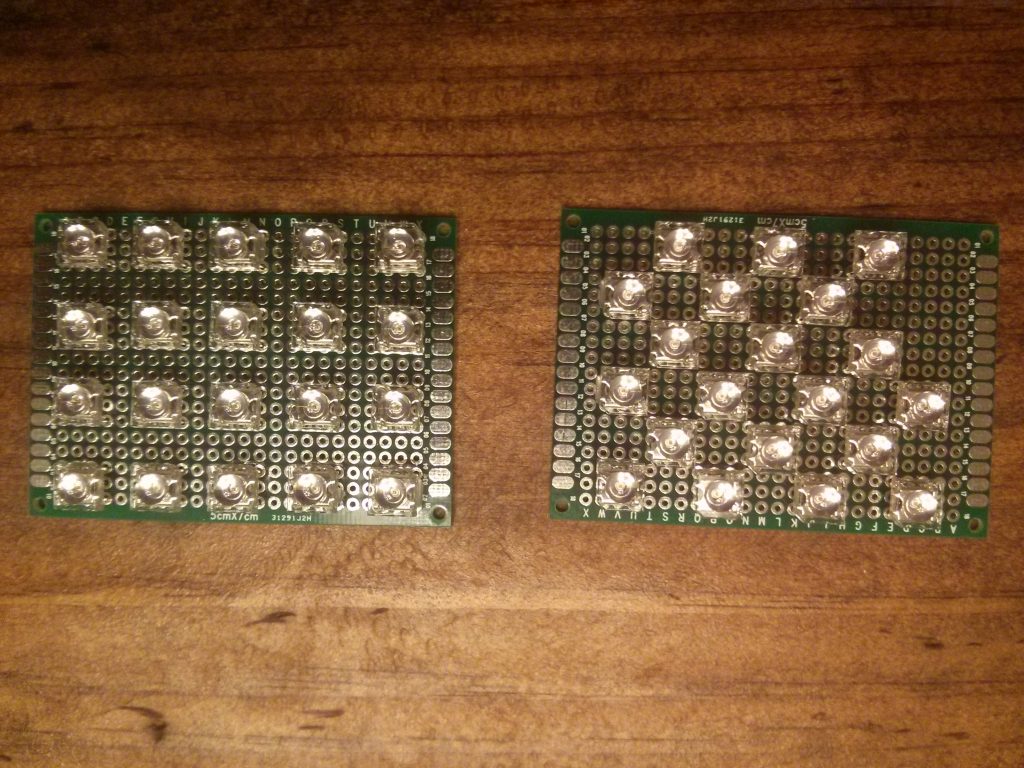
    I then started to experiment with LED layouts on my little project boards…

    Which is better?

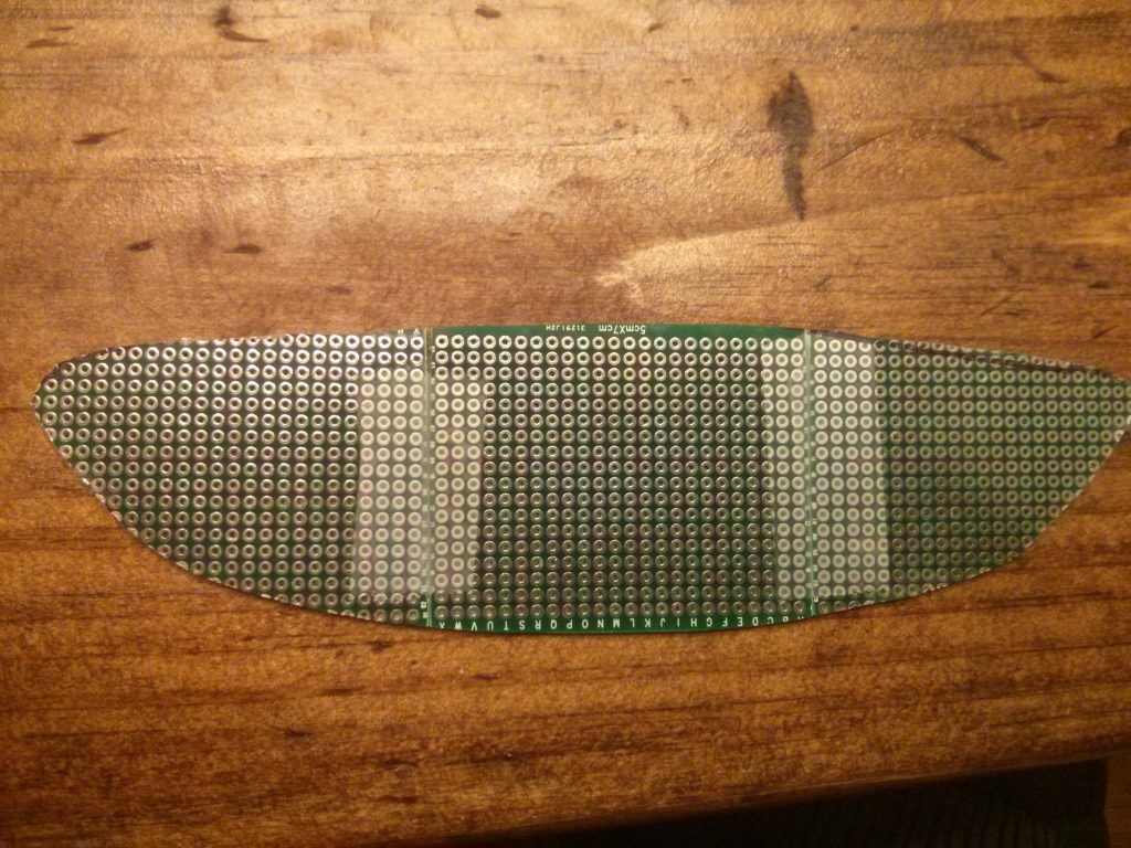
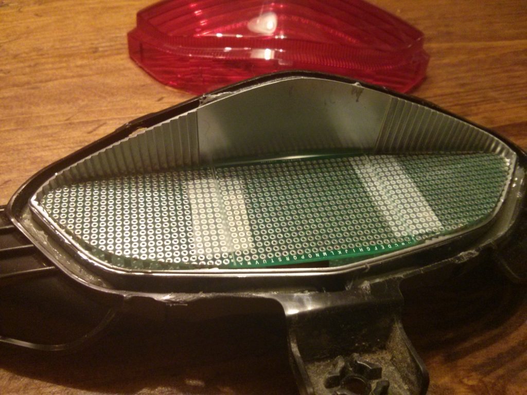
    And made a board that fits into my housing!  This took a bit of dremel-ing, tape, sanding, and patience.

    Then I attempted to place my LEDs on it in a nice manner.

    …And ran out of LEDs.  I’m ordering more.

  • New Motorcycle!

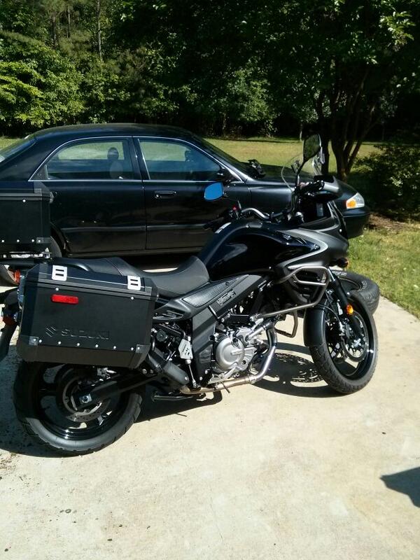
    A couple of weeks ago, I bought a 2012 Suzuki V-Strom 650 Adventure.

    First off, the engine is awesome.  Super flat torque curve.  It pulls just as hard at 3k rpm as 10k.

    What does this make for?  A bike that is way more enjoyable to ride than my 1992 Honda Nighthawk 750.  All the power on the Nighthawk is above 5k rpm–it feels dead at anything below that.  The ‘Stroms V-twin is just more my style of riding, similar to my 2003 Honda Shadow Spirit 750.

    And, safety.  After having a few close calls due to rear tire lockups and never using enough front brake, I thought it was time to get a bike with ABS, and this bike has it.  I haven’t had it kick in during emergency braking yet, but I’ve made sure that it works!  I’ll be much more comfortable riding 2-up.

    The price for a motorcycle this capable is great!  I feel like I came away with a brand new motorcycle for about half of what I would have paid at a dealer, and a new rear tire to boot.

    The range is great–This motorcycle also has a fuel gauge!  A 5.3 gallon tank means I should get around 290 miles to the tank if I run it dry.  I’ve been averaging about 55.1 mpg over the last couple of tanks, but I have noticed that cruising above 70 mph kills fuel economy, as to be expected.

    And, things I don’t like: for a motorcycle this new, where are my LED turn signals, running lights, and brake lights?  Motorcycles like this are already strapped for spare wattage, and if I want to add things like heated grips, gear, or auxiliary lights, I’ll need to free up some power.  Since the brake light bulb is a an 1157, it pulls about 20 watts when braking.  I can get that down to less than two watts using a custom LED array.  One of my buddies rides a 2005 BMW 650GS and it has LED brake lights, come on Suzuki!

    Another thing:  I’ve already bumped into a few things with the saddle bags.  This is more my fault than anything, as I’m not used to some wide bags on a bike.  Some bikes make it a point to have the hard bags the same or narrower than the handlebars, but Suzuki didn’t seem to care on this one.  I’ll just have to be more aware in the future.

    And lastly, while the V-Strom seat looks great, and feels great for about an hour, anything longer requires some off-saddle time.  I’ve still never ridden a motorcycle with a seat I’m in love with.

    And finally, a crappy picture of it:

    With ABS!
    My 2012 Suzuki V-Strom Adventure!