Category: Raspi Projects

  • Raspberry Pi Upgrade – WordPress Behind a Proxy

    Recently, I upgraded my Raspberry Pi that serves this website, my instance of EmonCMS, and a few other projects I use at home.

    As a part of that, I also use an instance of Home Assistant on a different Raspberry Pi.

    These things need to be available externally, which I struggled with at first. WordPress didn’t like responding in HTTP when it was hit with proxied/forwarded HTTPS requests over HTTP. This is post is to document what I had to do to fix this when future me has to fix the same problem.

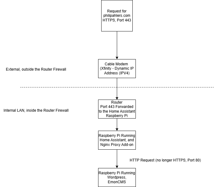
    Made in a free version of some Visio Online Tool

    As you can see, I used the first Raspberry Pi running Home Assistant responds to the domain ‘ha.philipahlers.com’. Nginx Proxy Manager sees other domains, like ’emon.philipahlers.com’ and ‘philipahlers.com’ and forwards them to the other Raspberry Pi. It’s getting HTTPS requests on port 443, handles the SSL certificates, and forwards the request, now HTTP and port 80 to that second Raspberry Pi.

    So to fix WordPress – I had to add some code to the WordPress wp-config.php file located in the WordPress installation folder:

    if (strpos($_SERVER['HTTP_X_FORWARDED_PROTO'], 'https') !== false) {
    $_SERVER['HTTPS'] = 'on';
    }

    This lets WordPress respond to requests forwarded from HTTPS over HTTP correctly.

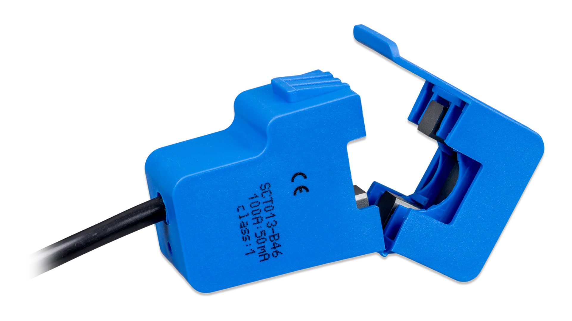
  • Current Sensing Transformers & EmonESP

    Current Sensing Transformers & EmonESP

    I’ve been upgrading my home power monitoring software a bit, as it looks like there are some new options out there for the ESP8266.

    Previously, I was using an ESP8266 with the Espressif AT firmware, available at their website: https://www.espressif.com/en/support/download/at

    Espressif also publishes an API reference for said firmware on their website as well. It looks like it’s even still being maintained – the AT Firmware API reference was last updated in August of 2020.

    You can see the code I used to interface with this AT firmware at my Github repository. Currently, that code runs on a Teensy 3.2 and pushes data using the AT firmware on the ESP8266 to an Emoncms server hosted on a Raspberry Pi. This method requires the generation of all sorts of AT commands and gibberish to get the ESP8266 to make a HTTP GET request to publish data to the Emoncms server. The main issue with this method was the fact that I was never able to get the ESP8266 to reliably reconnect to Wifi if the power went out. Essentially the ESP8266 would come up first, look for the Wifi network, get confused and just not play nice.

    I’ve been watching the development of EmonESP for a while – essentially the folks over at OpenEnergyMonitor wrote some great stuff that runs directly on the ESP8266 and provides a web UI that works great. What I’ve really been loving is the fact that there is a passthrough serial connection – so I can talk directly to my Teensy 3.2. This means I can remotely calibrate channels on the unit without re-flashing the unit, like I did before (great code writing by me… not).

    So after firing up Visual Studio Code with PlatformIO, I compiled the EmonESP for my device… and found a couple of issues. First, the path to the Emoncms server functionality was broken, so I made a fix and a pull request to get that fixed. Another issue was the fact that ArduinoJson (a great way to easily work with JSON on your Arduino or other microprocessor, FYI), declares sizing for objects up front – so the EmonESP implementation wasn’t cut out for my 20+ channels of data. Before, in src.ino in the EmonESP codebase:

      StaticJsonDocument<512> data;
    
      boolean gotInput = input_get(data);

    512 bytes got me about 16 channels of data + EmonESP diagnostic data. I’d like to keep the EmonESP diagnostic data it adds, plus some extra data for channels of temperature or other data. I sized it at 1024.

    This worked great! I’ve rewrote my code that runs on the Teensy 3.2 to hand off data in key:value pairs to the ESP8266 running the modified EmonESP software. That new sketch is located here.

  • Fusion 360 / Eagle PCB

    Fusion 360 / Eagle PCB

    It’s been a while since my last post! Every once and a while, I get a chance to sit down and work more on my power monitoring project. Previous versions of this project have been operational and collecting data for well on three years now, but I’ve wanted to clean up the physical design a bit and make it more usable.

    A quick recap of this project – my dad and I wanted something to monitor power usage in the home by each individual circuit in the house. Read about how these type of systems work at https://learn.openenergymonitor.org/.

    • I selected the Teensy 3.2 as my primary microprocessor to do ADC sampling and conversions as it has 21 ADCs
    • Selected the ESP8266 WiFi module to send gathered data to a database somewhere (using a local installation of EmonCMS on a Raspberry Pi)
    • Selected the Texas Instruments REF2033 as a voltage bias source (it’s expensive, but very nice for this application)
    • Used EAGLE to create schematics and the PCB layout
    • Sent PCB design files to SeeedStudio to be manufactured
    • Designed an enclosure in Fusion 360 with a snap-fit lid
    • Wrote (well, writing…) the code in the Arduino IDE

    A while back, North Carolina State University cut me off from using their Solidworks license – which makes sense – I graduated five years ago! In lieu of Solidworks, I picked up Fusion 360 at home (I use CATIA V5 at work).

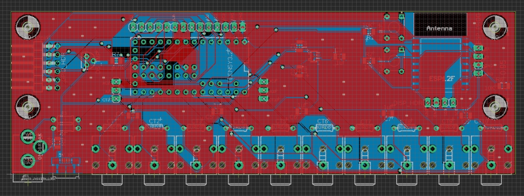
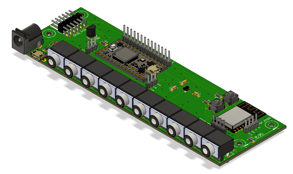
    Since I last used EAGLE, it was purchased by Autodesk and woven into their portfolio. As such, EAGLE now supports some 3D CAD integrations with Fusion 360. I’ve completed a revised version of my power monitor PCB layout – shown below in both EAGLE and Fusion 360. The combo of these two programs makes modeling PCBs and their supporting enclosure/structure very easy.

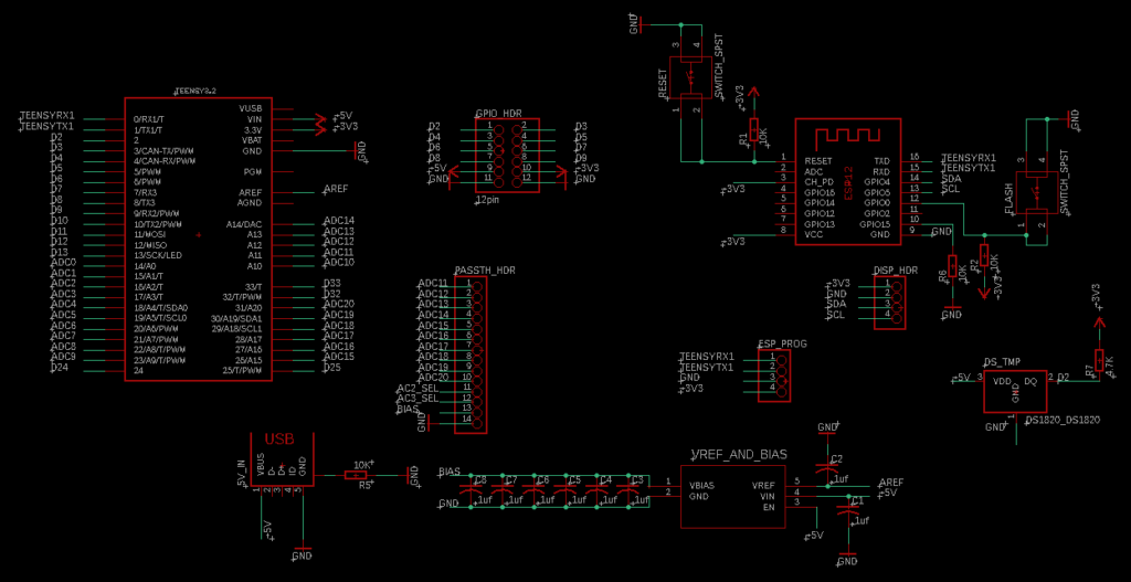
    A page from the schematic
    The EAGLE PCB Layout

    Once you have the PCB design complete, you can go in and update the 3D model of each component in EAGLE. You upload and position a custom model in the EAGLE interface. The interface to do this is a bit confusing, but I hear it will be getting better and more straightforward in the future.

    Then, you click a button in EAGLE that pushes the model to Fusion 360. As you can see below, if you’ve routed all your traces, it even shows them on the board, as well as all vias and other tiny details. It’s actually pretty sweet.

    Looks pretty good, right? It’s all in the setup in EAGLE to get the push to Fusion to look great.

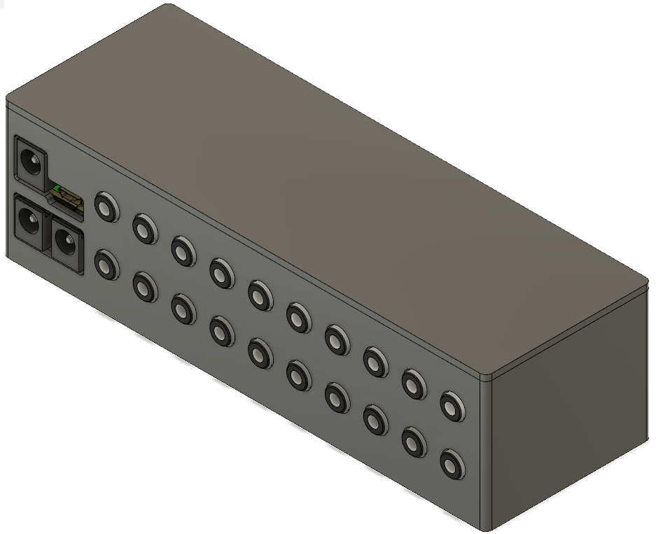
    This is what makes modeling enclosures super easy. In Fusion, you can actually project the board components onto sketches to drive geometry. Here’s a simple box I was able to come up with after couple of nights tinkering around:

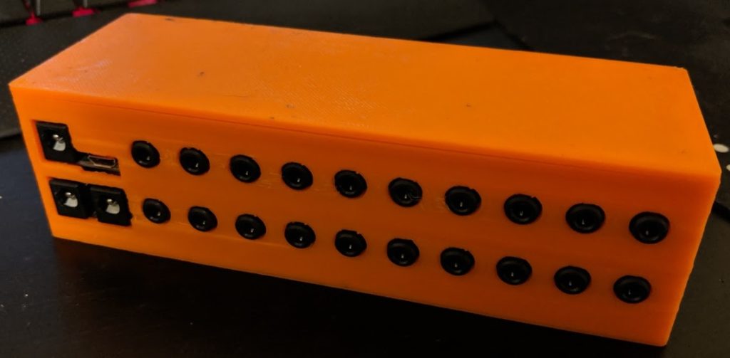
    In reality, the box will be orange (that’s the only color of filament I have for the 3D printer at the moment)

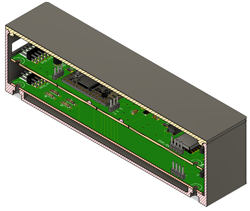
    And for reference a section analysis:

    Section analyses are great for verifying you’ve got everything to fit!

    Sliced it up and printed it on my Qidi Tech I (A Flashforge/Makerbot clone):

    Orange.

    Now to update the software that runs on this bad boy…

  • PCB SolidWorks 3D modeling

    PCB SolidWorks 3D modeling

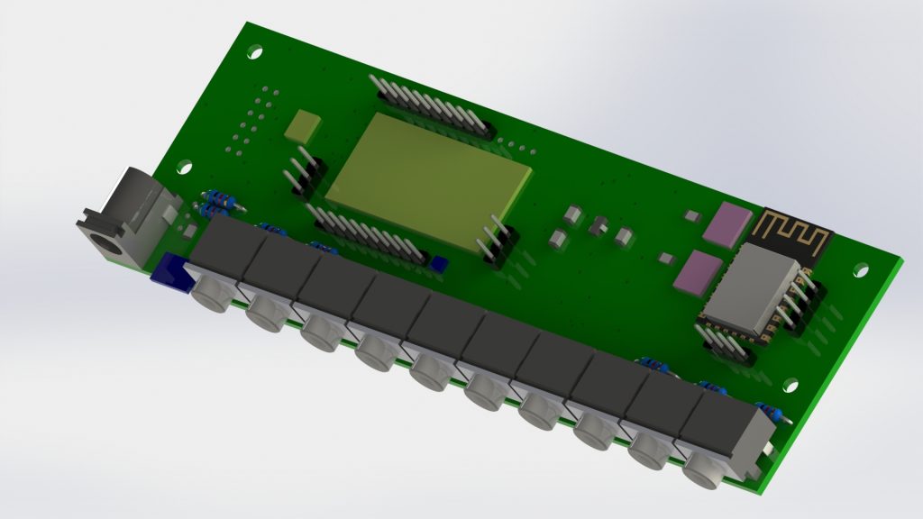
    This is actually work from a while ago – but I wanted to share this. I’ve been working on a new version of the Power Monitor PCB that uses an ESP8266 and Teensy 3.2. Here’s the board mocked up in SolidWorks CircuitWorks:

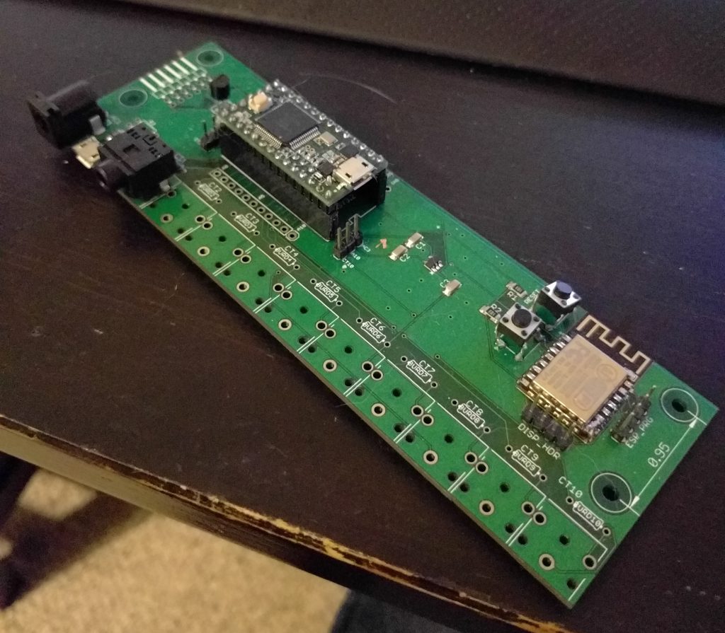
    And here’s the board in real life, with only a couple of components on it:

    Pretty neat, right?  You can spend as much time as you want in SolidWorks CircuitWorks to get everything as photo-realistic as possible. The important thing is to get component heights, sizes, and locations right to make the design of an enclosure easier.

  • WebSocket Apache Proxy

    WebSocket Apache Proxy

    I recently installed a cool tool called Node-RED which is a neat visual coding tool for IoT-type devices. It uses node.js, and listens on port 1880.  However, I wanted Node-RED to function over port 80, to avoid having to type a port as part of the URL. I struggled getting the WebSocket connection to function correctly. I kept getting a HTTP response of 500.


    I figured I might be able to save some other folks the trouble (and help me remember for next time). To get this to work on a system running Apache, you’re going to need to enable a few modules.  I’m running Apache 2.4 on Raspbian Jessie for context.

    sudo a2enmod proxy
    sudo a2enmod proxy_http
    sudo a2enmod proxy_wstunnel
    sudo a2enmod proxy_html
    sudo a2enmod proxy_fcgi


    And configure your site listener to include the lines:

    ProxyPreserveHost On

    ProxyRequests Off


    ProxyPass /nodered http://localhost:1880

    ProxyPass /nodered/comms ws://localhost:1880/comms


    ProxyPassReverse /nodered http://localhost:1880

    ProxyPassReverse /nodered/comms ws://localhost:1880/comms


    I learned where the WebSocket connection failed by watching the Javascript console in Chrome – it points you to the /comms directory, so you need to enable the WebSocket proxy there.

    This way, you can simply navigate to your Node-RED installation on port 80 by simply using the URL http:///nodered/

  • Power Monitoring Code

    There are two chips that make up this board – the Teensy 3.2 and the ESP8266. The ESP8266 in this setup runs the AT firmware, which allows communication over serial using a published API. The API documentation is available here. To flash the ESP8266 with the AT firmware, Expressif (the manufacturer) has a tool available on their website.

    The default baud rate of the most recent AT firmware is 115200. This can be changed, but the faster the better, right?

    To use the Arduino IDE to program the Teensy 3.2, you can download Teensyduino, available from here.

    So now our environment for programming this combo is ready!

    To test the connection between the ESP8266 and the Teensy 3.2, you can throw on a simple passthrough sketch, and manually type in AT commands into the serial monitor. (also for some reason I can’t figure out the WordPress code formatting)


    void loop() {
    // Send bytes from ESP8266 -> Teensy -> Computer
    if ( Serial1.available() ) {
    Serial.write( Serial1.read() );
    }
    // Send bytes from Computer -> Teensy -> ESP8266
    if ( Serial.available() ) {
    Serial1.write( Serial.read() );
    }
    }

    Make sure you put initialize both serial ports to 115200 in setup().

    The complete code is available at https://github.com/fillycheezstake/PowerMonitor. It’s a WIP, so don’t judge too hard.

  • Thermostat datalogging reboot/major update

    I had a post a while ago talking about how I log the thermostat data from a couple of thermostats located at my parents home.

    Well, take a look at the new thermostat.philipahlers.com!

    This URL actually points to a separate Raspberry Pi (an older Model B) than the one that this site runs on.

    I’ve updated the UI & added some stats calculations. What other stats could be useful for thermostats? I’ve thought of:

    • Average deltaT
    • Average daily temperature
    • Number of cycles

    I’m no pro with nice looking web design or CSS, but I know enough to be dangerous. Also working to have the CSS reside in it’s own external file – right now there’s some in supporting php files, as well as inline in the HTML. I need to work on my coding style!

    The code is located here, as a GitHub repo.

    See any bugs? (I’m working to fix a security issue).

  • Motorcycle Computer: The Screen Module

    Motorcycle Computer: The Screen Module

    I recently found some pictures of construction that I thought I lost, so I’ll be able to do a simple breakdown of the components.

    First – this shelf from AdventureTech, LLC.  Here’s the link to the product page. They’ll even cut holes in it for you, although I cut my own.

    From AdventureTech, LLC
    Image is from AdventureTech, LLC

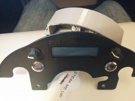
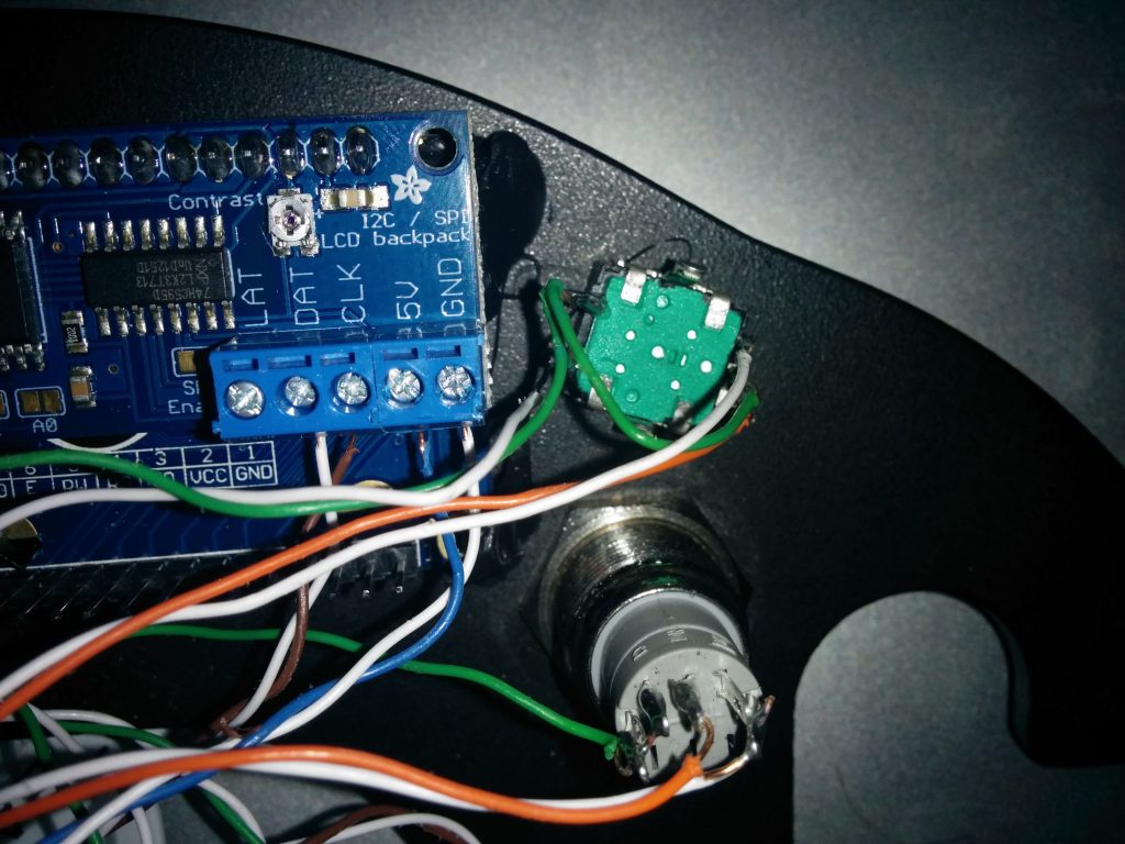
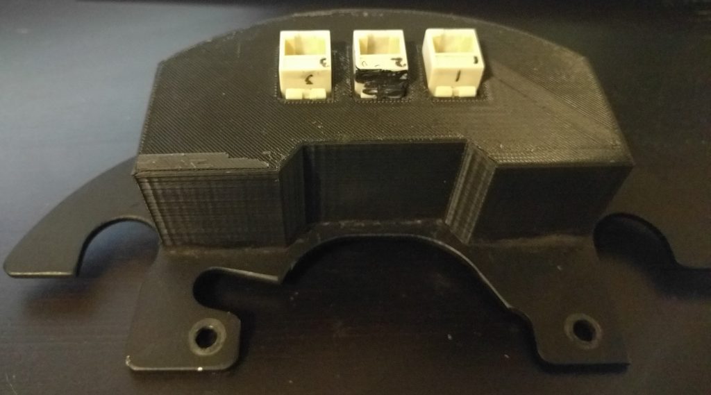
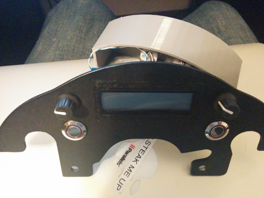
    Once I had the shelf – it’s just a nice powder coated piece of aluminum – I cut out a rectangle for the LCD, and drilled holes for the buttons and rotary encoders I planned to use. Then I soldered wires to all the terminals I’d need – and then routed them to Cat5e jacks, so the actual computing power would be somewhere else on the bike.

    Part of this meant I’d need something to keep the electronics safe and hopefully dry. I modeled a cover in SolidWorks and used a Makerbot Replicator 2 to 3D print a cover. The SolidWorks file is here. I used Black Permatex RTV to seal any openings.

    As stated in another post (this one) I needed to remove I2C from the equation, so that I2C backpack was later removed.

    Here’s a quick parts list:

    • 2x Rotary Encoder – Link
    • 2x LED Button – Link
    • 1x LCD – Link
    • 3x Cat5e Jacks
    • Suzuki V-Strom Shelf (AdventureTech, LLC) – Link
    • 3D Printed Cover
    • Black RTV
  • Motorcycle Computer, Try Number 1

    Motorcycle Computer, Try Number 1

    If you check out the post Heated Jacked PWM Controller, you’ll notice that while I’ve figured out the electronics behind this, I’d yet to figure out the logistics behind a computerized controller.

    The original plan used a Raspberry Pi A+, and also used a Adafruit LCD I2C Backpack. This actually made it to a few test rides on the bike.  It worked! Well, sometimes…

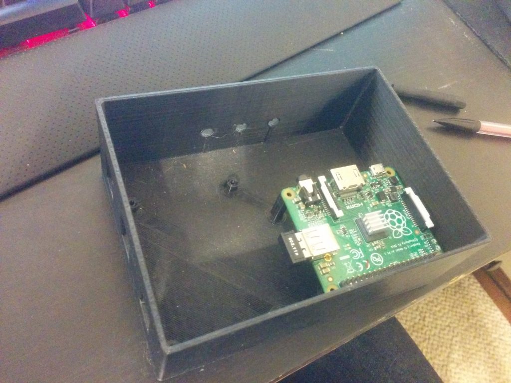
    Short story – This box sat under my seat and housed the Raspberry Pi, MOSFETs, and power supply. This is after I disassembled the first failed attempt.

    This unit mounts to my handlebars (and this pic actually has some testing going on).

    Originally, I wanted to control the box using as few wires as possible – the screen takes six (not counting the backlight colors), and each encoder needs two, each button needs one, and buttons need ground. The I2C backpack made controlling the screen possible with only two wires, so I was able to get it down to <16 conductors, or two Cat5e cables.

    BUT – read anything about I2C (which I failed to do) – and you’ll realize a shortcoming.  It’s extremely susceptible to any magnetic or electrical interference. It’s really designed for chips residing on the same PCB.

    So the end result of the Raspberry Pi based system: it worked only when the bike was off. No kidding – without the bike on, there was no interference on the I2C lines, and the screen worked perfectly. I even had a little screen configured to graphically represent the setting of the jacket. The MOSFET worked great, and so did the rotary encoders. For a peek at that old code, see my github repository.

    If the I2C line started seeing errors and missing commands, the screen would display gibberish. Unfortunately, that was really anytime the bike was running. Turns out, metal spinning, fuel pumps pumping, and high-voltage spark plugs firing doesn’t make it a good environment for sensitive protocols like I2C (that’s why things like CAN bus exist). These I2C errors would then make my program hang.  I could have coded some I2C refreshes in, but it doesn’t solve the root cause.

    Back to the drawing board – for a hardware update.

  • Heated Jacket PWM Controller

    Along with owning a fuel-injected motorcycle comes rapid cold-weather starts, as the bike’s fuel mapping takes into account ambient temperature and other environmental factors.  Carbureted engines have lacked this auto-adjusting ability, even with the advent of electric chokes.  And with these nice, smooth cold weather starts – I don’t ever want to stop riding my motorcycle!

    So I recently purchased Gerbing heated jacket liner.  You can buy a controller from Gerbing for ~100 bucks.  But I wanted to do something a little more DIY.  If you did this right, you could build your own heattroller (as they’re called) for around ~15 bucks (555 timer, MOSFET, resistors/capacitors, wiring, but more on my build).

    Essentially, we need a way to switch the jacket on and off in varying degrees, depending on how hot we want the jacket. Why not use a variable resistor, you say? Stay tuned for a lesson on resistance and power. Switching something on and off is much more efficient.

    Enter PWM, or Pulse Width Modulation.  Some may have heard of this technology to dim LEDs, vary the speed of electric motors, or control servos in RC applications.  Essentially, a square wave is generated.  If you don’t know what a square wave looks like, see the Wiki page.  This square wave can be generated at any frequency.  Now, if the square wave spends half it’s time at max amplitude and the other half at zero potential, the duty cycle is 50%.  The longer the square wave is at max amplitude, the higher the duty cycle.  So that’s how we’ll control the on-off action of the jacket current – by increasing or decreasing the duty cycle.

    Choosing a frequency, however is interesting.  For a heated jacket, which has a lot of ‘thermal inertia’ or what I like to call it–in that it doesn’t heat up or cool down super quickly (Gerbing says it takes 4 seconds to reach max temperature) our frequency for the PWM can be fairly low.  I’m using 1 Hz.  Other devices, like LEDs, need to be driven at a much higher frequency because they don’t have any ‘inertia’ (not super sure what word to use here).  Why make it low?  Our later discussion of MOSFETs – switching losses.  Read about it here.

    But we have another problem – what can I generate the PWM signal with?  A 555-timer can be used as an astable oscillator that generates a PWM signal, with the same amplitude of what the 555 timer is powered with.  But a 555 timer can only sink about 200ma of current.  The Gerbing heated jacket liner is rated at 12v and 6.9A.  So we need a sort of relay, or switch to do the actual on-off, and a PWM signal source.

    For my motorcycle, I’m attempting to build a trip computer / recorder out of a Raspberry Pi.  The Raspberry Pi has GPIO pins which can be used to generate a PWM signal at any frequency or duty cycle.  I won’t have to fabricate a 555 circuit!  But we still will need a high-current switch.  A transistor, MOSFET, or even a relay could work at these slow PWM frequencies.  I wanted a solid state option, so I looked around for a MOSFET.

    Laying around in my electronics bin, I had a few of these:  BUZ91A.  Protip:  don’t ever buy these.  I tried to use one, and it promptly got so hot it nearly destroyed itself.  Why?  Take a look at the datasheet – the Rds(on) is .9 ohms!  That’s a lot.  And we know that

    P = V * I and V = I * R

    Thus,

    P = I * R * I

    P = I2 * R

    What does this mean?  Our jacket drawing 6.9 Amps would mean the MOSFET would have to dissipate nearly 43 Watts.  Not what you would call efficient or safe.  That would take a fairly large heatsink.  So after some looking around, I decided to purchase a few of these.  The Rds(on) is only .028 ohms.  Now, the MOSFET only should need to dissipate less than 1.4 Watts.  That’s a bit of an improvement, I’d say.  It probably won’t even need a heatsink with that load on it – especially since heated jackets are only used when the ambient temperature is <50degF.

    For more info, you can read the Wiki page on PWM.

    Or read up on some Ohms law (this site was awesome in college)!