I recently found some pictures of construction that I thought I lost, so I’ll be able to do a simple breakdown of the components.
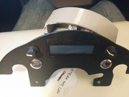
First – this shelf from AdventureTech, LLC. Here’s the link to the product page. They’ll even cut holes in it for you, although I cut my own.
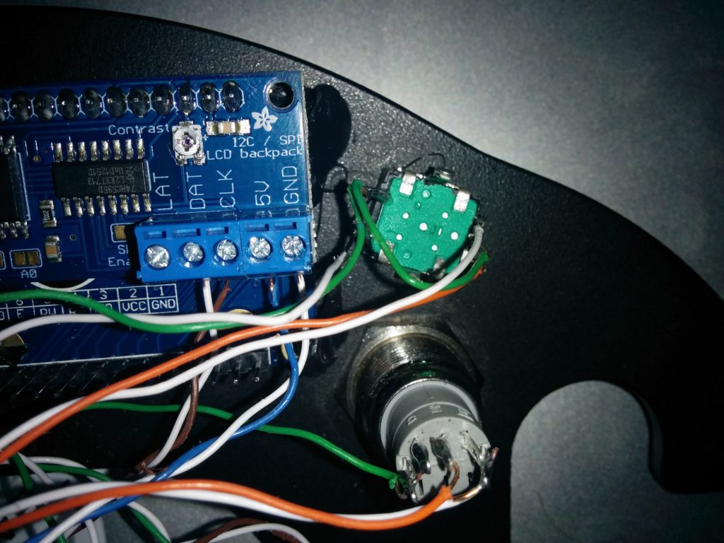
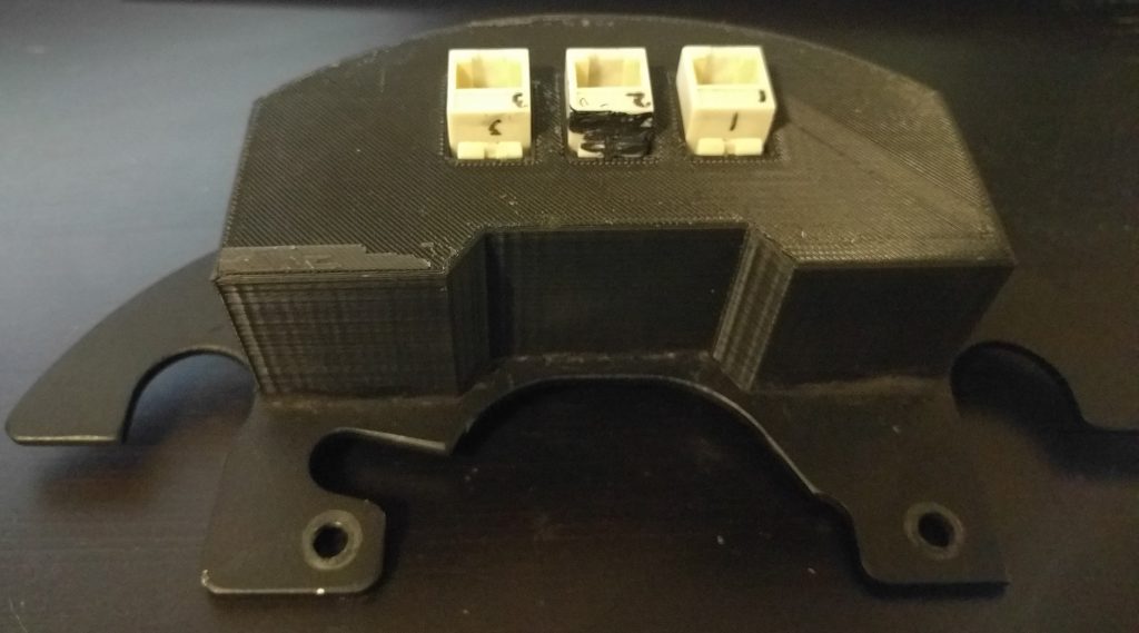
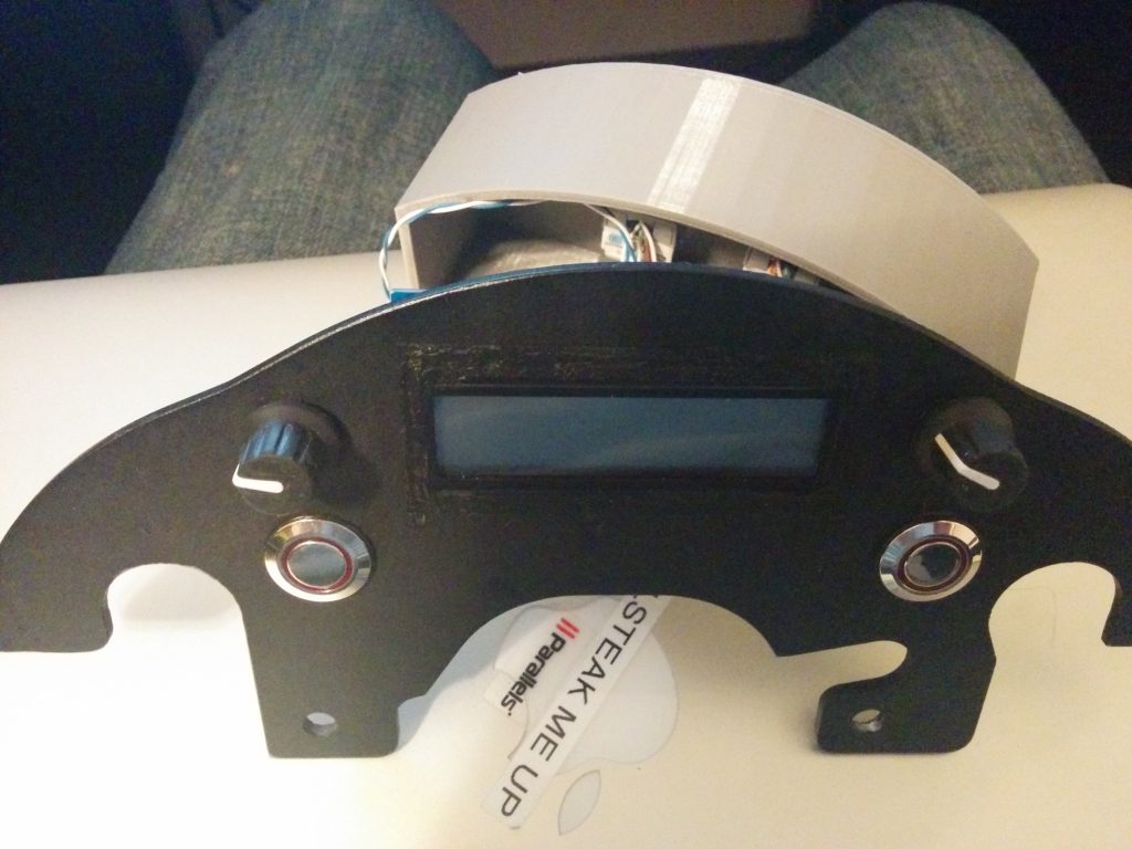
Once I had the shelf – it’s just a nice powder coated piece of aluminum – I cut out a rectangle for the LCD, and drilled holes for the buttons and rotary encoders I planned to use. Then I soldered wires to all the terminals I’d need – and then routed them to Cat5e jacks, so the actual computing power would be somewhere else on the bike.

Part of this meant I’d need something to keep the electronics safe and hopefully dry. I modeled a cover in SolidWorks and used a Makerbot Replicator 2 to 3D print a cover. The SolidWorks file is here. I used Black Permatex RTV to seal any openings.
As stated in another post (this one) I needed to remove I2C from the equation, so that I2C backpack was later removed.
Here’s a quick parts list:
Comments
One response to “Motorcycle Computer: The Screen Module”
[…] many more features and ADC inputs in a much smaller package. I use the same board in my revamped Motorcycle Computer project. Its 3.3v regulator can also support the ESP8266’s power requirements. […]